

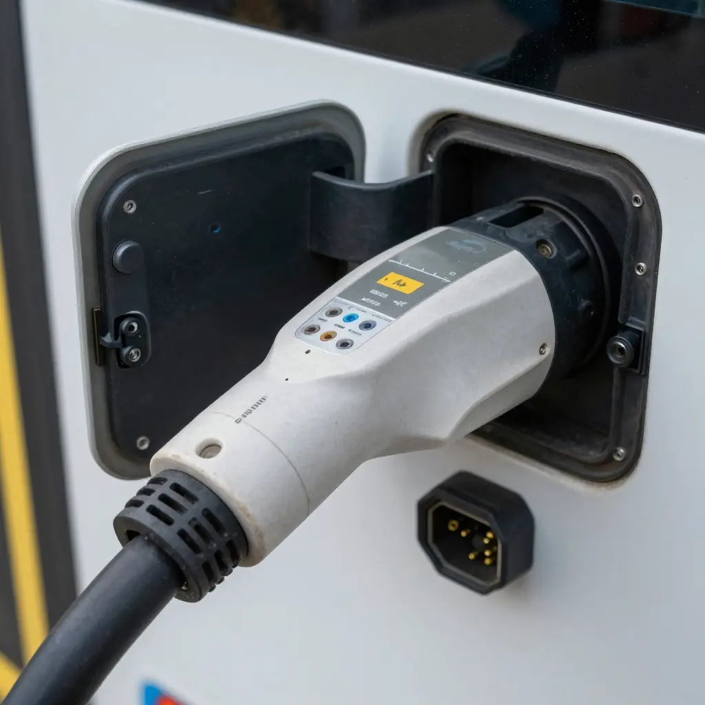
Repeated plug cycles, not a single overload event, are what crack charging connector pins. In the high-power DC connectors used by transit fleets, a pin can see thousands of mating cycles, and each one adds a little mechanical and thermal stress. Over months of daily depot charging, that stress accumulates until cracked pins quietly degrade performance.
- This analysis is for auto repair shops, electric bus manufacturers, and transportation companies.
All three meet the same failure mode from a different angle. Repair shops replace worn connector assemblies, manufacturers design pins for longer service life, and operators watch how catching charge-point faults early reveals wear before it spreads.
Connector Pin Anatomy
A charging connector pin is a precision assembly, not just a metal rod. At its core sits the contact body, usually a machined copper alloy that carries current. The plated contact surface – typically silver or hard gold – resists corrosion and keeps contact resistance low. A retention spring presses the mating halves together and holds normal force through thousands of plug cycles. The rear termination is a crimp or a threaded joint that bonds the pin to its cable. An insulating housing aligns every pin and blocks arcing.
Pins differ by duty. A DC fast charging contact power pin often runs 8-12 mm in diameter to carry 200-500 A. Signal pins are far thinner, around 1-3 mm, and handle only milliamps for communication. Ground pins sit in between, sized to match fault current. Repeated cycles fatigue these parts, and cracks often start where a crimp meets the contact body.
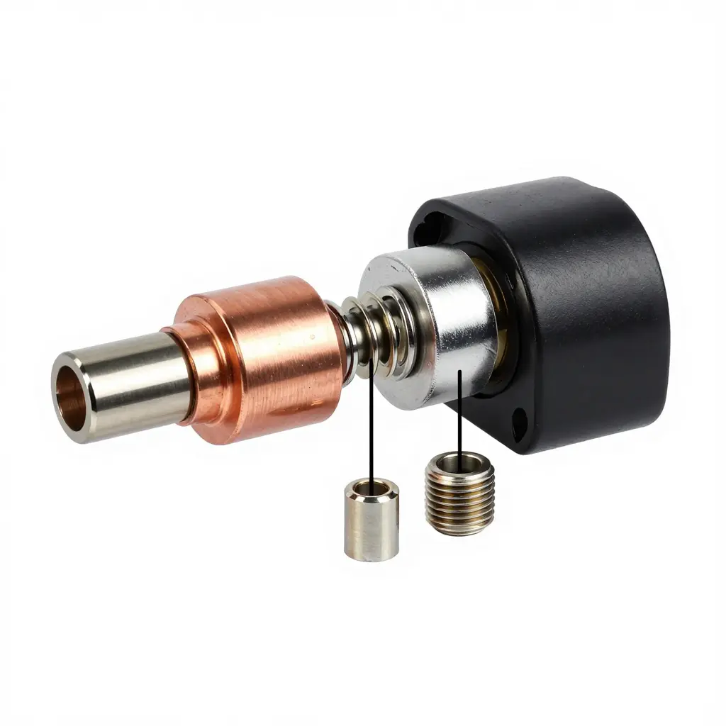
Watching these pins degrade over time lets crews catch early charge point faults before a failure strands a bus.
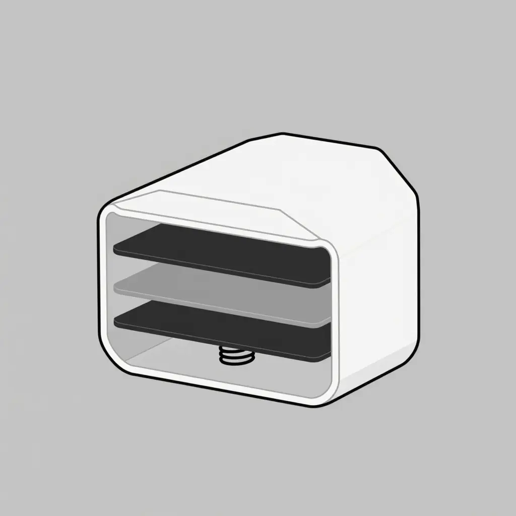
Inside a Single Connector Pin
A charging pin is four functional layers stacked together, and each one decides how well the pin survives repeated plug cycles:
- Outer housing – the protective shell that aligns the pin during insertion and shields the assembly from dust, water, and debris.
- Plated contact surface – a thin conductive coating that carries current across the mating interface. It is the layer that wears down first.
- Solid contact body – the structural core. It holds the shape of the pin and bears the mechanical load of every plug-in.
- Retention spring – the element that keeps the pin seated and maintains contact pressure inside the housing.
Cycle a connector hundreds of times a day and stress builds at the boundary between the plated surface and the solid core. Catching that wear early – the same logic behind electric bus telematics that catch charge point faults – is the first step toward preventing a pin from cracking.
What Happens During a Single Plug Cycle
Every time an electric bus connects to a charger, one plug cycle runs through the same mechanical sequence. Each phase loads the male pins and female sockets differently, and repeated plug cycles accumulate fatigue at the contact interface.
- Insertion force – The driver seats the male pins into the female sockets, compressing spring contacts. Peak force spikes when alignment is off, bending pins instead of letting them slide.
- Contact wipe – Pins travel a few millimeters, wiping oxide and debris from the interface. This motion keeps resistance low but abrades plating with every pass.
- Retention engagement – Latches lock the connector, holding steady spring pressure while current flows and thermal rise builds. Heat softens the metal, weakening it cycle by cycle.
- Withdrawal – Latches release, pins slide out, and the wipe repeats in reverse.
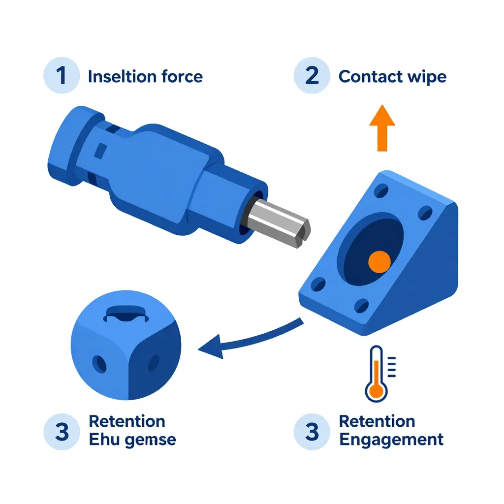
Under normal mating, load spreads evenly across all pins. Misaligned or partial insertion concentrates force on a few contacts, so those pins overheat and crack sooner. Telematics that catch charge point faults early give crews a way to spot that pattern before it repeats.
Connector Pin Failure Modes at a Glance
Before you replace a whole charging cable assembly, know what killed the pins inside it. The table covers the five most common failure modes in high-cycle electric bus charging connectors: the trigger behind each one, the symptom you can see, and the field test that confirms the diagnosis.
| Failure Mode | Likely Trigger | Visible Symptom | Detection Method |
|---|---|---|---|
| Fatigue cracking at the crimp | Repeated plug cycles plus vibration flexing the cable-to-pin joint | Hairline crack at the crimp barrel; pin feels loose in the housing | Visual + magnification, dye penetrant, pull test, X-ray/CT scan |
| Stress corrosion cracking | Road salts/humidity acting on residual tensile stress in the pin alloy | Branching cracks, dull discoloration along grain boundaries | Metallography, SEM, micro-hardness survey |
| Contact surface fretting | Micro-motion between mated contacts under load | Dark oxide film, pitted or blackened contact faces, rising voltage drop | Contact resistance test, SEM/EDX analysis, thermal imaging |
| Thermal cracking from arc heating | Arcing at high inrush current or partial/incomplete mating | Melted crater, heat discoloration, carbonized insulation | IR thermography, arc-fault signature logging, resistance trend |
| Mechanical deformation from misalignment | Forced insertion, worn guide pins, bent mounting bracket | Bent or skewed pin, deformed sleeve, stiff plug-in feel | Dimensional gauge, alignment fixture, plug-force measurement |
Footnote – standards context: Pin geometry, torque limits, and required mating-cycle endurance depend on your region: CCS (SAE J1772 / IEC 62196-3), CHAdeMO (IEC 62196-3), and GB/T (GB/T 20234.1 and 20234.3). A pin that fails well before its rated cycle count usually points to a violated spec, such as an over-torqued crimp or an out-of-spec mating force. Fleets tracking intermittent connector faults across a depot can use charge-point telematics to flag early resistance drift before a pin cracks outright.
Why Pins Crack: A Fatigue and Thermal Story
Look closely at failed electric bus charging connectors and the damage rarely starts at the surface. Every insertion and withdrawal flexes the pin, and thermal cycling during charge and cooldown expands and contracts the metal. Arc-induced heating at imperfect contact points adds sharp localized spikes, and plating wear strips away the coating that once spread current evenly. Together these forces seed micro-cracks that grow with each cycle, an accumulation of metal fatigue across thousands of plug cycles. Ambient and depot temperatures change the failure rate dramatically: cold mornings stiffen housings and raise insertion force, while hot depots accelerate oxidation and soften contacts. Field inspections confirm the pattern, as units cycling several times daily fail far sooner than lightly used ones. Cracked pins therefore signal a fatigue and thermal problem rather than a design defect alone, which is why charge-related warranty disputes so often trace back to connector stress.
Cumulative Pin Crack Incidents vs. Plug Cycles
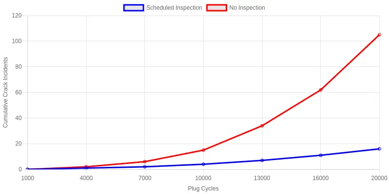
The chart tracks two connector populations from 1,000 up to 20,000 plug cycles. Connectors kept on a scheduled inspection regime creep upward almost imperceptibly, reaching roughly 16 cumulative crack incidents by 20,000 cycles. Connectors with no inspection track close to them until about 10,000 cycles, when the curve bends and accelerates sharply – 15 incidents at 10,000 cycles, then roughly 105 by 20,000. In this dataset, crack incidents accelerate after a threshold near the 10,000-cycle mark.
For fleet operators and repair shops the point is simple: the early cycles hide the damage, so wear that looks harmless at 7,000 cycles can turn into an avalanche of failed pins a few thousand plugs later. Pairing scheduled physical inspections with remote monitoring – the condition data described in this overview of electric bus telematics catching charge point faults – catches that inflection point before it compounds.
Charging Connector Pin Inspection Checklist
Charging connector pins work harder than any other part of an electric bus depot. Every plug cycle scrapes, heats, and stresses them, and after thousands of sessions the damage is invisible to a quick glance. A disciplined inspection routine catches small faults before they cascade into arcing, melted housings, or a stranded bus. The checklist below is written for repair shops, fleet operators, and manufacturers who want consistent, repeatable results. Work through it with the connector de-energized, cleaned, and well-lit, and log every finding so trends show up before failures do. Between manual checks, many depots pair this routine with telematics that flag charge point faults automatically.
- Measure contact resistance with a micro-ohmmeter and compare against the manufacturer baseline; a rising value signals pitting or looseness.
- Inspect for discoloration, blistering, or a rainbow sheen on the pin surface, all early signs of overheating.
- Look for hairline cracks at the pin base and inside the insulator, using magnification under bright light.
- Verify retention force with a pull test to confirm each pin still seats and locks securely.
- Clean contamination such as dust, carbon tracking, and dried dielectric grease that masks damage or raises resistance.
- Check pin alignment and depth so the mating sequence stays even across all contacts.
- Examine the housing and seals for water ingress, corrosion, and cracks around the pin bores.
- Measure temperature rise under a load test to spot hotspots a visual check can miss.
- Review plug cycle counts and duty logs to flag connectors approaching replacement intervals.
- Document every pin’s condition with photos and readings so wear trends become visible over time.
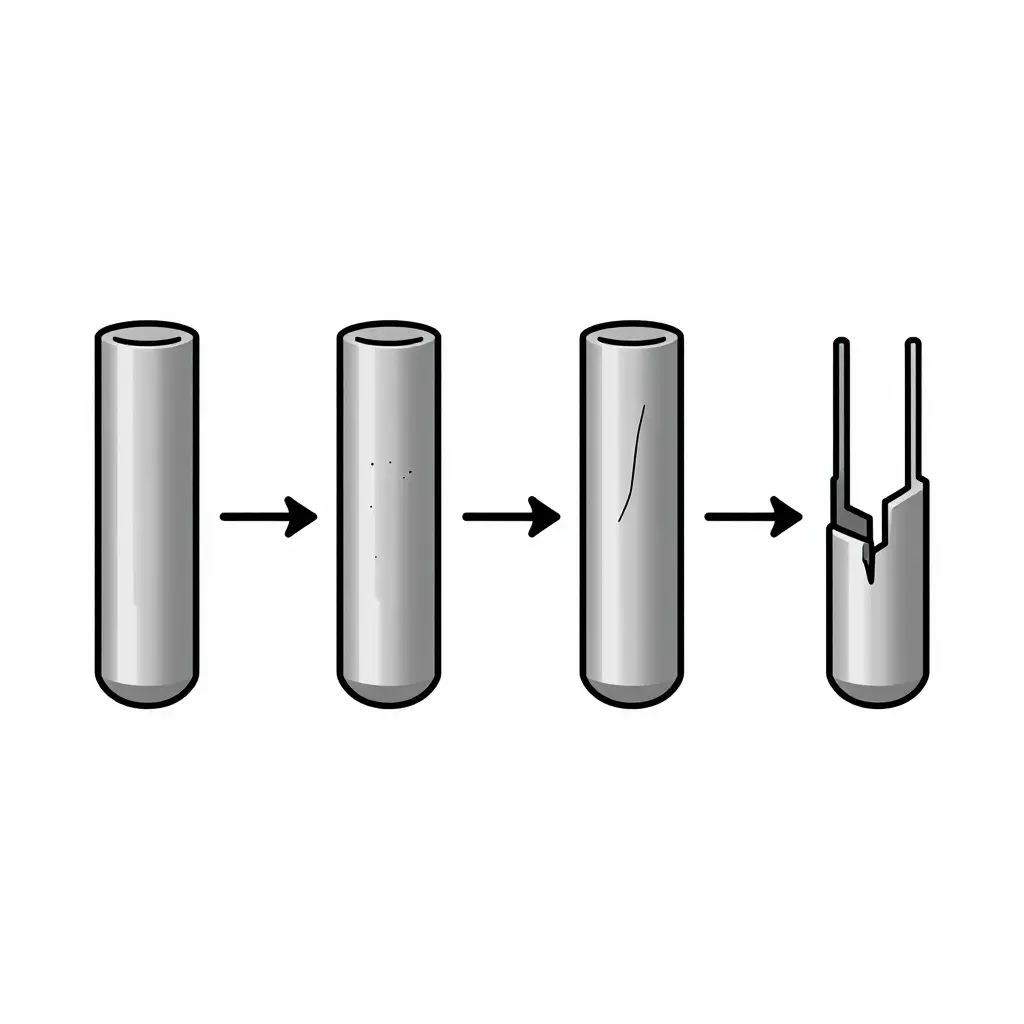
Pin Failure Progression: From Healthy Contact to Cracked Pin
The diagram traces how a charging connector pin degrades across repeated plug cycles, from a healthy contact to a full fracture and power loss. Each stage is a checkpoint where an inspection or a fault signal can catch the problem before it becomes a service call, so read it alongside the root-cause analysis and the failure-mode table.
How to Read the Four Stages
- Stage 1 – Smooth contact surface: A new or healthy pin with an even, polished mating face. Resistance is low and current transfer is stable.
- Stage 2 – Surface fretting marks: Micro-movement between pin and socket during each plug cycle rubs away the plating, leaving fretting wear and small pits.
- Stage 3 – Hairline fatigue crack: Cyclic mechanical and thermal stress opens a thin crack, usually near the pin base where stress concentrates.
- Stage 4 – Full crack and power loss: The crack propagates through the pin, breaking the circuit, causing arcing, and triggering shutdown or charging failure.
Stage 2 is the cheapest point to intervene, so pairing visual inspections with smart charge-point monitoring helps fleets catch fretting before it becomes a fracture. Tools such as electric bus telematics for catching charge-point faults can flag the rising contact resistance that appears at Stages 2 and 3.
Maintaining and Repairing Cracked Pins
Prevention is cheaper than repair. Build scheduled contact resistance testing into every charging connector maintenance routine: measure micro-ohm readings each quarter and flag any pin drifting above baseline before heat and arcing set in. When you find cracked pins, choose deliberately. Re-crimping works for loose, intact terminals, but once a pin is physically fractured, replace it outright – a fresh crimp will not restore full current capacity.
Always torque connector hardware to the manufacturer’s specification (typically 8-12 Nm for high-current lugs), because under-torquing accelerates fatigue. Retire a connector when resistance climbs steadily, housings show melting, or pins crack again soon after repair.
The math favors prevention: a scheduled inspection costs a few technician hours, while unplanned charger downtime can idle an entire electric bus fleet. Electric bus telematics that flag charge-point faults catch those problems early, when the fix is still a pin rather than a charger.
Design and Material Choices That Reduce Pin Cracking
For manufacturers, the most effective fix starts at the drawing board. An electric bus charging connector design built for longevity combines four elements: higher-durability plating (hard-silver or silver-over-nickel) to resist wear and arc erosion; spring-loaded contact systems that maintain consistent normal force as pins heat and expand; precision alignment guides that prevent the lateral stress that bends and cracks pins during misaligned insertion; and better thermal management at the contact interface to lower peak temperatures. Validating these choices requires accelerated plug-cycle testing (e.g., per SAE J3105, IEC 62196, and UL 2251 regimes), where thousands of simulated insertions reveal fatigue long before field failure. Material behavior shifts with temperature, and plating hardness and contact resistance change in cold depots, so designers should also examine how cold-climate conditions alter charger output and mechanical stress.
FAQ: Charging Connector Pin Cracking
How many plug cycles before pins typically crack?
There is no single fixed number, because pin life depends on connector design, current load, and how carefully operators insert the plug. In heavy-duty electric bus depots, most charging connector pins begin to show fatigue cracking somewhere between 10,000 and 30,000 plug cycles. High-power DC connectors used several times a day can reach that range within two to four years.
Can cracked pins be repaired or must they be replaced?
Cracked pins should always be replaced, not repaired. Field soldering, filing, or bending can hide the damage for a short time but weakens the pin’s conductivity and mechanical strength, and it usually voids the connector warranty. Because a cracked pin can arc and overheat, swapping out the pin or contact assembly is the only safe option.
Do fast charging and heat shorten pin life?
Yes. Fast charging pushes higher current through each pin, and the resulting heat accelerates metal fatigue and oxidation, so pins crack sooner than on slow-charge connectors. Repeated thermal cycling from high-power sessions expands and contracts the pin material until small fractures form, which is a common reason disputes arise over fast-charging damage. Worn or undersized contacts make the problem worse by raising resistance at the interface.
How do you tell a cracked pin from a worn contact?
A worn contact usually shows uniform flattening, discoloration, or a loose fit, while a cracked pin has a visible split, often near the base or tip where stress concentrates. Use a magnifier to check for hairline fractures, and watch for unusual resistance or localized heat build-up on individual pins. Worn contacts can sometimes be cleaned or re-tensioned, but cracked pins must be replaced outright.
Repeated plug cycles drive fatigue and thermal cracking in charging connector pins, and no single remedy fully solves it. The fix is a combination: scheduled inspection, correct maintenance, and better connector design.
Repair shops catch worn pins before they strand a vehicle. Manufacturers extend connector life through robust materials and clear maintenance guidance. Transit operators protect daily uptime with proactive monitoring and timely replacement.
Connector durability standards should also move toward realistic cycle testing and clearer ratings, so electric bus charging connectors become long-lasting assets rather than recurring costs.