

Electric Bus Depot Fire Codes: Where Charger Placement Meets Ventilation
Electric bus depot fire codes combine local building regulations, national electrical and fire standards, and insurance requirements covering how battery-electric buses are stored, charged, and protected indoors. They set the rules for detection, suppression, separation distances and, for fleets moving off diesel, ventilation. Those codes are being revised faster than operators can rebuild the depots they already own.
Charger placement sits at the center of that pressure. Where charging equipment goes is an electrical decision, but not only that: position, density and orientation determine how heat, off-gas and smoke are expected to move through an enclosed bay, and the ventilation design is built around those expectations. Move a row of outlets closer to a structural wall, stack more units into one bay, or add a fast-charging pillar, and the airflow assumptions behind the original design no longer hold.
Ventilation retrofits are therefore often triggered by repositioning chargers inside an existing depot. A change that reads as a minor electrical adjustment – and is usually planned alongside broader depot power upgrades – can push a facility past a code threshold, requiring new extraction capacity, different detection zoning or wider suppression coverage.
For depot managers and safety compliance officers, charging layout and fire safety cannot be planned in separate silos. Because the two are linked, treating charger placement as a fire-safety variable from the start is the cheapest way to avoid a disruptive retrofit later.
The Regulatory Framework Behind Depot Fire and Ventilation Codes
Before arguing about where a charger goes, it helps to know what the rules are actually trying to control. Electric bus depot fire codes are rarely written around products: regulators almost never name a charger brand or a bus model. They regulate space, hazard, and airflow – the physics any combination of vehicles and equipment has to satisfy. Two depots with identical fleets can therefore face very different requirements, depending on how the building is classified.
How the Framework Is Structured
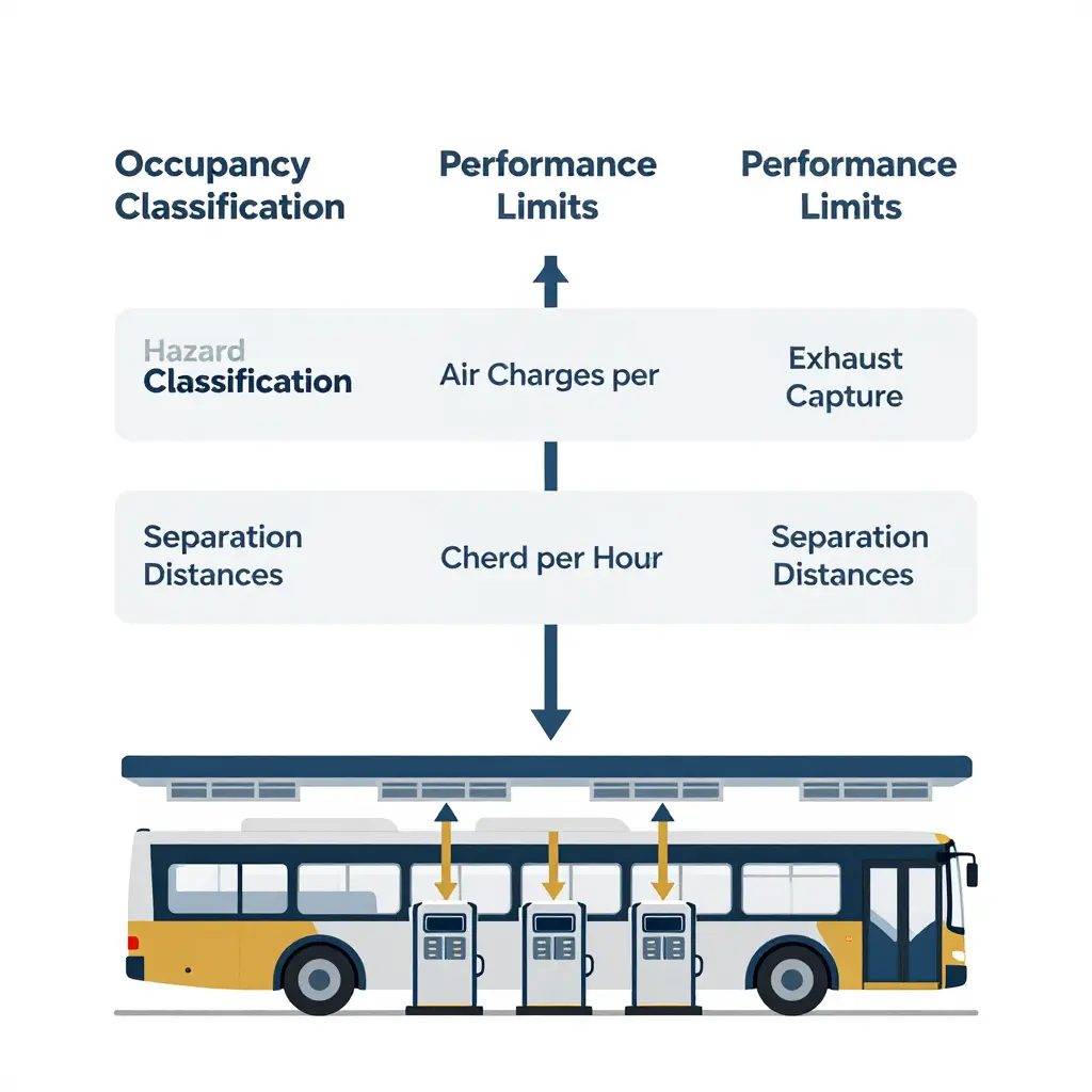
Most codes build requirements in three layers, each resting on the one above it:
- Occupancy classification – A depot is classified by how the space is used and who occupies it. This sets the baseline for egress, detection, and suppression systems.
- Hazard classification – Because lithium-ion packs store large amounts of energy and can enter thermal runaway, facilities are typically pushed into a higher hazard tier. This drives more stringent protection.
- Performance thresholds – The hazard tier is then translated into measurable limits: air exchange rates, setback distances, and containment requirements.
The code itself is technology-agnostic. What matters is how much heat, gas and smoke a space could release, and how the building removes or contains it – not which vendor supplied the equipment.
Fire Safety Codes and Lithium-Ion Risk
Traditional fire codes were written with diesel and its liquid fuel load in mind. Lithium-ion batteries behave differently. They can off-gas combustible vapor before ignition, and a single cell in thermal runaway can propagate to its neighbors, producing sustained heat that water alone may not fully suppress.
Codes respond to this by asking designers to demonstrate control of three things:
- Early detection – identifying off-gassing or rising temperature before a full event develops.
- Gas management – preventing the accumulation of flammable vapor in enclosed bays.
- Containment and separation – limiting how far a single event can spread.
Mechanical Ventilation Standards and Air Changes per Hour
Mechanical ventilation is where hazard classification turns into a number. The usual metric is air changes per hour (ACH): how many times the full volume of a space is replaced each hour. Codes may also set a minimum airflow for normal operation and a higher emergency rate that detection systems can call for.
A depot designed for a low ACH figure may need a ventilation retrofit once charging is added or densified, because more energy in the same volume raises the airflow required.
Exhaust Capture Near Chargers and Separation Distances
Two further concepts shape layout decisions:
- Exhaust capture near chargers – local extraction close to the point where off-gassing is most likely, so vapor is drawn away before it can spread across the bay.
- Separation distances – minimum spacings between parked vehicles, chargers, and walls, intended to slow propagation and preserve access for responders.
Where chargers sit determines how far exhaust capture has to reach and whether separation distances can be kept. On tight footprints, that overlap usually shows up first as a power and infrastructure constraint – the bottleneck covered in this look at why depot power upgrades stall.
What This Means for Planners
The regulatory foundation is deliberately structure-based: classify the space, classify the hazard, then hit a measurable airflow and spacing target. Get those three layers right, and the specific hardware becomes a design choice rather than a compliance gamble.
Why Charger Placement Dictates Ventilation Design
Charger placement is the input that defines the ventilation strategy of an electric bus depot. Every charger is a continuous heat source; during a thermal event it is also a potential ignition point and a source of off-gas. Where the chargers stand decides where those hazards concentrate.
Heat, off-gas, and fire load follow the chargers
- Heat: Power electronics, cables and connectors release waste heat during every charging session.
- Off-gas: A failing lithium-ion cell vents flammable and toxic gases that ventilation must exhaust, never recirculate.
- Fire load: Dense charging concentrates stored energy, raising the worst-case fire load in a single zone.
That is why intake and exhaust points have to be aligned with the charger positions. Intake should deliver clean make-up air to the equipment and the operator’s breathing zone; exhaust should sit above the chargers, where rising heat and buoyant off-gas collect. Misaligned, the air you pay to move never reaches the hazard it was sized to control.
Uniform chargers vs. clustered charger banks
The two placement patterns demand opposite airflow strategies:
| Configuration | Hazard distribution | Required airflow strategy |
|---|---|---|
| Uniformly distributed chargers | Low, diffuse, spread across the bay | Broad, low-velocity dilution airflow with distributed intakes and exhausts |
| Clustered charger banks | High, localized, concentrated in one zone | Focused, high-velocity local exhaust – hoods or slot extraction – at the bank |
Uniform placement favors dilution: large volumes of air moved gently to hold concentrations below threshold everywhere. Clustered banks favor capture: strong local extraction that grabs off-gas before it drifts sideways toward buses, batteries or people.
Why a layout change triggers a retrofit
A ventilation layout is engineered against one specific charger arrangement. Move a bank, add a row, or switch from distributed posts to a central charging hub, and the heat, off-gas and fire-load profile the system was designed for no longer exists – a previously compliant layout can become non-compliant almost overnight. That gap is why ventilation retrofits happen, and why electric bus depot fire codes increasingly tie approval to the two systems being designed together. Charger-driven retrofits also tend to arrive alongside broader depot power and infrastructure planning, since added airflow, extraction and detection all draw on the same electrical and mechanical backbone.
Ventilation retrofit needs shift dramatically depending on how chargers are arranged across a depot, so the table below maps each common layout against its practical compliance implications.
| Charger Configuration | Typical Charging Power Range | Primary Ventilation Challenge | Likely Retrofit Scope | Relative Compliance Difficulty |
|---|---|---|---|---|
| Single-row curbside chargers | 50-150 kW | Localized heat and off-gas pockets along the curb line | Ducted extract near each curb position; minor airflow rebalancing | Low |
| Double-sided central island chargers | 60-180 kW | Heat trapped between opposing bays; limited cross-draft | Central extract canopy plus aisle air-supply upgrades | Moderate |
| Clustered high-power charger banks | 150-600 kW | Concentrated thermal load; rapid smoke accumulation | Dedicated high-capacity exhaust; fire-rated separation | High |
| Overhead pantograph charging points | 200-600 kW | Rising heat plume and smoke above the bus roof | Roof-level stratification exhaust; smoke reservoir design | High |
| Distributed end-of-bay chargers | 30-120 kW | Uneven airflow; dead zones at bay ends | Zonal extract fans; sensor-based airflow control | Low to Moderate |
Ventilation has to handle both routine heat and worst-case off-gassing, so charger placement decides how much ductwork, exhaust capacity and detection a site ends up needing. Grouping high-power equipment pushes projects toward major retrofit scopes; spread-out low-power layouts usually need lighter modifications. Since ventilation scope tends to track the available power supply, review depot power upgrade planning before locking in a final charger layout.
How Charger Placement Expands the Scope of a Ventilation Retrofit
Charger placement looks like a layout decision, but it behaves like a hazard-classification one. Slide a bank of chargers from an open apron into a partially enclosed bay – or the other way around – and smoke, heat and flammable gas behave differently. Because most electric bus depot fire codes base ventilation requirements on the enclosure around the charging equipment rather than the charger itself, the whole ventilation retrofit package moves with the chargers.
Duct routing
In an open apron, smoke and gas disperse into ambient air and extraction can be handled by low-level pickups near the charger base. Put the same chargers inside a bay and the ceiling becomes the collection zone: hydrogen and other buoyant gases rise and stratify up there. Duct routing then has to reach the highest points of the space, avoid ceiling pockets where gas stagnates, and keep runs short enough to preserve capture velocity.
Exhaust fan capacity
Enclosing the chargers raises the air-change rate the system has to meet. A layout sized for an open apron may get away with intermittent boost extraction; a partially enclosed bay usually needs continuous-duty fans rated for a worst-case gas release. Capacity, redundancy and the ability to keep running through a power fault all rise together.
Makeup air provisions
You cannot exhaust air you cannot replace. Tighter enclosures need engineered makeup air – louvers, transfer ducts or tempered supply – so the fans do not starve and pull the space negative, dragging smoke into adjacent zones.
Detection sensor density
Open aprons tolerate sparse sensing because gas disperses freely. Enclosed bays need denser arrays: hydrogen and gas detection high up, heat and smoke detection across the bay, and coverage mapped to the actual charger placement so no pocket goes unmonitored.
Emergency shutdown interfaces
Relocation changes shutdown logic too. Chargers inside a bay have to trip on gas or heat alarms, isolate the affected circuit and coordinate with the extraction system. Electrical load becomes a planning constraint here – the same infrastructure limits that stall depot power upgrades often decide how much shutdown and monitoring capacity the retrofit can support.
Why the direction of the move matters
Moving chargers into an enclosure almost always expands the retrofit package. Moving them out can shrink it, but only if gas dispersal, drainage and detection keep pace. The dimensions move together, rarely one at a time.
| Retrofit dimension | Open apron | Partially enclosed bay |
|---|---|---|
| Duct routing | Localized low-level pickups | High-point ceiling extraction |
| Exhaust fan capacity | Intermittent boost | Continuous duty, worst-case sizing |
| Makeup air | Natural infiltration | Engineered paths to avoid negative pressure |
| Detection sensor density | Sparse | Dense, multi-layer arrays |
| Shutdown interfaces | Manual or localized | Automatic trip tied to alarms |
Key Considerations for Planning Ventilation Retrofits
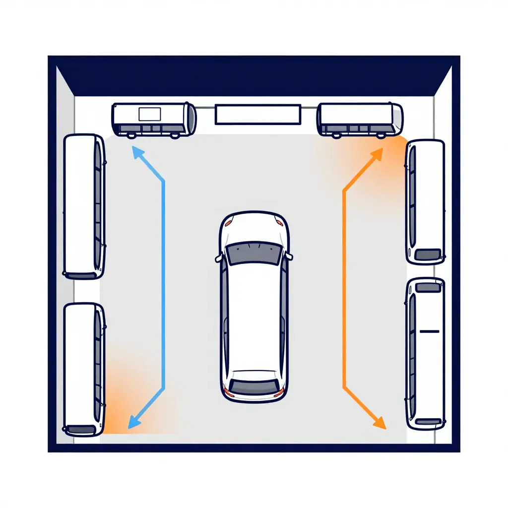
When charger placement shifts across a working depot, the ventilation strategy usually has to shift with it. The checklist below is for keeping a facility aligned with current electric bus depot fire codes.
- Re-verify air change rates against the updated hazard classification. A change in hazard class can invalidate the original design, so recalculate the required air changes per hour and compare them with your existing mechanical capacity before ordering new hardware.
- Confirm exhaust capture proximity to charger clusters. Extraction hoods and fans should sit close enough to the densest high-risk clusters to remove hydrogen or smoke at the source instead of letting it drift across the bay.
- Check detection and alarm coverage. Verify that gas, heat and smoke detectors reach every reconfigured bay; relocating chargers can leave blind spots in the original sensor layout.
- Plan a phased charger relocation to limit downtime. Sequence the moves so only part of the fleet is offline at any time and revenue service keeps running.
- Coordinate electrical and ventilation permitting together. Bundling power and airflow approvals avoids the stalls that happen when one inspection lands before the other is ready – a common reason depot power upgrades stall electric bus fleets.
- Document your assumptions for inspectors. Keep a clear record of design calculations, hazard classifications and airflow figures so compliance officers can demonstrate due diligence on demand.
Working through the list early keeps a retrofit predictable, defensible and ready for inspection.
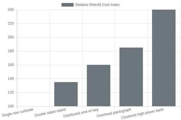
The pattern is clear: the more tightly high-power chargers are clustered into one bank, the steeper the ventilation retrofit bill. Clustered high-power layouts cost roughly 2.4 times the baseline set by single-row curbside stalls. Distributed end-of-bay positions land in the middle of the range, while overhead pantograph designs cost more again, because airflow has to be managed above the bus rather than at floor level. Layouts that concentrate thermal load in one zone trigger stricter smoke-extraction and air-change requirements, and those requirements drive the spend. Deciding on a layout early, with ventilation thresholds and depot infrastructure upgrades in view, is one of the cheapest decisions a depot manager can make.
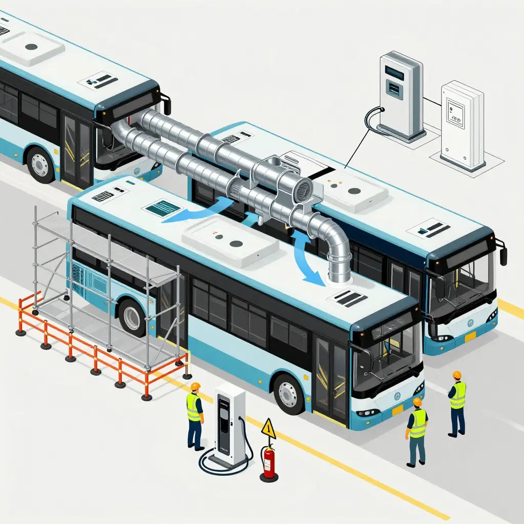
Ventilation retrofits rarely happen in a quiet, empty depot. Buses still have to roll out, drivers still have to plug in, and safety schedules still apply. That overlap is where the difficulty starts. Design is one problem; delivery is another, and delivery happens while the site keeps operating.
Keeping the Depot Running
Most operators cannot shut the depot down. Retrofitting ductwork or upgrading extraction in one bay while the rest of the site stays live takes strict zoning, temporary barriers and revised traffic flows. Dust, hot work and restricted access slow turnaround, and a blocked lane can ripple into the next morning’s pull-out.
Temporary Charging Arrangements
Teams often bring in temporary dispensers during construction. They keep vehicles moving, but they also change the assumptions the original charger placement was based on. A relocated unit may sit closer to stored buses or intrude on a fire lane, creating fresh compliance gaps while attention is elsewhere.
Structural Limits on Ducting
Not every depot was built to carry extra ducting. Roof loads, beam spacing and congested ceiling services can block straightforward routes, so adding extraction may mean reinforcing structure or re-threading runs around existing cables and pipes. Each workaround adds cost, time and inspection risk.
Fire Code and Electrical Capacity
Fire code compliance and electrical capacity often pull in opposite directions. More extraction means more dedicated power, while faster charging raises demand the existing supply cannot meet. When deadline pressure pushes crews toward aggressive charging, that urgency can clash with safety schedules and strain battery terms – a tension examined in this discussion of battery warranty and fast-charging disputes.
The Cost of Lost Charging Cycles
Every hour a bay is offline is charging capacity lost, and lost cycles push fleets into peak-hour catch-up charging. Real-time fault detection, as covered in catching charge point faults with telematics, lets managers spot failures early and redeploy vehicles before a small outage becomes a service disruption.
| Challenge | Operational Impact | Practical Mitigation |
|---|---|---|
| Partial depot operations | Slower turnaround, blocked lanes | Phased zoning and revised site traffic plans |
| Temporary charging | New fire-lane and clearance risks | Re-check spacing after every relocation |
| Structural ducting limits | Added cost and schedule delay | Early structural and services surveys |
| Code vs. electrical capacity | Conflicting upgrade requirements | Align fire and power design up front |
| Lost charging cycles | Reduced daily range availability | Fault monitoring and flexible dispatch |
Handled well, these constraints turn a disruptive retrofit into a sequenced project rather than a scramble.
Compliance Verification and Inspection Readiness
Once a ventilation retrofit is commissioned, the burden of proof shifts to the operator. Demonstrating that a system satisfies electric bus depot fire codes is ongoing work, not a one-time event: inspectors want to see that what is installed matches the approved design, that it performs under real conditions, and that both can be shown on demand. Here is how depot managers and safety compliance officers stay inspection-ready.
Documentation Expectations
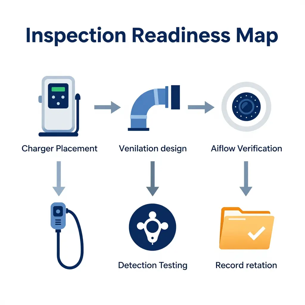
Inspection readiness starts with paperwork that mirrors reality. Keep one version-controlled package that a code official can follow from charger placement to final airflow readings. A complete set typically includes:
- The stamped charger placement drawing showing every unit’s location and power rating
- The ventilation design narrative and duct layout tied to that drawing
- Baseline and post-install airflow measurements in cubic feet per minute (CFM) per bay
- Detection and alarm commissioning test records with dates and technician names
- The commissioning report, sign-off sheet, and any authority-having-jurisdiction (AHJ) correspondence
Airflow Verification
Measure capture velocity and CFM at each charging bay, then compare the results against the design intent. Record the method, the instrument used and its calibration dates so the numbers hold up under scrutiny.
Detection Testing
Prove that gas, smoke and thermal detection trigger correctly and that interlocks – such as charger shutdown or increased fan speed – activate as designed. Record every test, including any failures and the corrective action taken.
Record Retention
Keep commissioning records, test logs and maintenance history for the full life of the system. A searchable folder structure saves hours when an inspector requests eighteen months of detection tests in a single visit.
Mapping Findings Back to the Charger Layout Drawing
Most inspection findings trace back to the charger placement drawing. When a detector sits outside a coverage zone or a duct misses a bay, the cause is usually a mismatch between where chargers actually stand and where the drawing says they do. A stale drawing turns a minor tweak into a full re-review, delays the certificate of occupancy and invites repeat findings, so the drawing and the ventilation design have to stay synchronized.
Closing the Emergency Response Loop
Finally, confirm that local responders know the layout as well as you do. Share the current drawing and ventilation plan with the fire service, and coordinate water supply planning so the on-site response matches what your detection system will trigger. Understanding the water capacity a fire engine needs for depot response is part of aligning suppression strategy with the ventilation retrofit. With the drawing and the response plan in sync, the compliance loop closes.
Key Takeaways
- Keep one version-controlled documentation package, not scattered files
- Verify airflow and detection against the approved design, not assumptions
- Retain records for the system’s full life cycle
- Always map findings back to a current charger placement drawing
- Synchronize the drawing, ventilation design, and response plan before every inspection
What the Split Tells Us
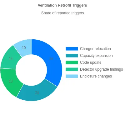
Charger relocation alone accounts for roughly a third of all ventilation retrofits, by far the largest single trigger, because moving a charger shifts the relationship between heat sources, cable routing and air-change pathways. A layout decision made during planning sets the ventilation requirement years later, which is why charger placement sits at the center of most electric bus depot fire codes. For the second-largest slice, capacity expansion, the related infrastructure stress usually shows up first as delayed charging, as covered in our look at why depot power upgrades leave electric bus fleets stranded.
Frequently Asked Questions: Electric Bus Depot Fire Codes and Charger Placement
How does charger placement affect required ventilation rates?
Where chargers sit changes how much air has to be moved and where. Chargers clustered in an enclosed corner trap heat and any battery off-gassing, so electric bus depot fire codes typically demand higher air-change rates in those tight zones than in open, spread-out layouts. Spacing chargers along a ventilated wall or near ceiling extraction points lowers the ventilation burden and reduces hotspots, which makes placement one of the cheapest ways to shrink the requirement.
Do I always need a full retrofit after moving chargers?
No. A relocation triggers a major ventilation overhaul only when the new position changes the hazard profile, for example moving chargers into a tighter bay with a lower ceiling. If airflow paths, clearances and extraction coverage stay intact, a modest adjustment or a re-verification may be enough. Targeted upgrades are usually far cheaper and faster than replacing an entire system because charger placement changed.
How long does a typical ventilation retrofit take?
Timelines vary, but most depot-scale ventilation retrofits run from a few weeks to a few months depending on scope. Simple modifications, such as adding extract fans or ducting, can be done in days or weeks; full redesigns involving structural work or new control systems stretch longer. Permitting, inspection scheduling and equipment lead times often add more time than the installation itself, so it pays to plan for the depot power upgrades these projects frequently require.
Can an existing depot reach compliance without reconstruction?
In many cases, yes. Compliance is about outcomes – air-change rates, detection coverage, clearances – not about erecting new buildings. Operators regularly satisfy electric bus depot fire codes by retrofitting ventilation, adjusting charger placement and upgrading detection instead of demolishing and rebuilding. A thorough assessment usually shows where targeted improvements close the gap.
What documentation do inspectors look for?
Inspectors want proof that design intent matches what is actually installed. Expect to provide ventilation calculations tied to charger placement, equipment specifications, commissioning records and maintenance logs. Clear as-built drawings showing airflow paths and charger locations make the review far smoother, and current records also make it easier to demonstrate ongoing compliance when electric bus depot fire codes are updated.
How does charger placement interact with detection and suppression?
Placement determines where detection and suppression hardware can do the most good. Grouping chargers lets you concentrate thermal cameras, gas sensors and suppression nozzles on the highest-risk spots; scattered placement leaves blind areas. Designing charger placement and fire systems together means detection triggers faster and suppression reaches the source before a fault spreads, which is one reason ventilation retrofits and fire-system upgrades are best planned as a single project.
Further Reading
Managing an electric bus depot, or overseeing its safety compliance, runs well beyond charger placement. The resources below cover the equipment choices, cleaning practices and fleet operations that keep a charging yard safe, well-ventilated and ready for anything – all worth reviewing alongside your work on electric bus depot fire codes.
Fog cannon truck selection guide – walks through specification decisions that shape how quickly a depot can cool a battery fire and clear smoke from an enclosed charging bay.
Fog cannon truck versus water sprinkler truck comparison – contrasts two suppression approaches so you can pick the method that best complements the ventilation retrofits your site is planning.
Road sweeper truck selection guide – helps fleet operators keep yards free of the grit and debris that can clog ventilation intakes and obscure safety signage around chargers.
Largest fire truck overview – offers a practical benchmark for understanding the reach and limits of heavy suppression apparatus within tight depot layouts and access routes.
Taken together, these guides cover the equipment and housekeeping side of a safer, smoother-running depot.
Bringing It Together: Placement and Ventilation as One Strategy
Charger placement is an electrical decision with design consequences. What gets drawn on the layout sheet carries into ventilation, detection, egress and long-term operating cost, and planning ventilation retrofits into the original depot design is almost always cheaper, faster and safer than bolting them on after vehicles are already plugged in.
The Takeaways
- Regulatory framework: Fire codes treat active charging zones as high-risk areas, so ventilation, gas and heat detection, and egress paths must all be sized to the layout you choose. Understanding electric bus depot fire codes early turns a vague obligation into a concrete engineering brief.
- Cost differences by layout: Centralized, distributed and combination arrangements carry very different ventilation price tags. Retrofitting after installation consistently costs more than designing for airflow up front, which is why charger placement deserves attention at the concept stage, alongside planned depot power upgrades.
- Practical planning checklist: Map charger positions, model heat and gas dispersion, confirm clearances, and coordinate with fire authorities before construction begins.
- Compliance verification: Treat airflow testing, detector calibration and periodic inspection as living records that stay current as the fleet and layout evolve.
When charger placement and ventilation design are aligned from day one, a depot protects both operational continuity and occupant safety. Reacting afterward invites outages, rework and regulatory friction that a little foresight would have avoided.
Depot standards are moving toward performance-based guidance that expects operators to demonstrate measured airflow, documented dispersion modeling and integrated monitoring rather than simply tick a box. Depots that treat placement and ventilation as one deliberate design decision today will be better positioned when those rules tighten.