

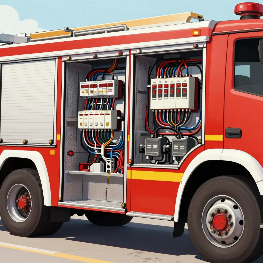
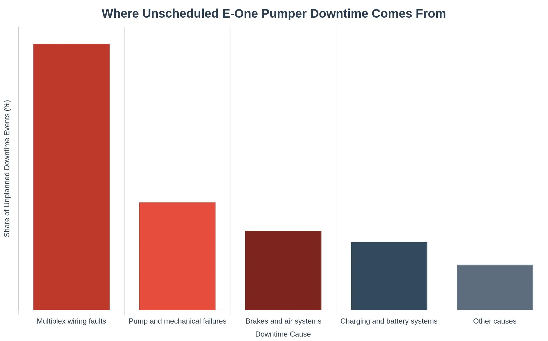
E-One pumper downtime rarely starts with a mechanical pump failure. In most fire apparatus fleets, the dominant cause of unplanned downtime and lost availability is the multiplex wiring and electrical control system, not the fire pump. A multiplex fault cuts the shared data and power paths that link the chassis, pump, and operator panel, costs more to diagnose than a worn impeller or a leaking seal, and happens far more often.
For fleet managers, fire chiefs, and apparatus maintenance technicians, that distinction decides what you budget for, what you stock on the shelf, and when you schedule service. Plan maintenance around pump rebuilds and ignore the electrical architecture, and you will keep losing trucks to a failure mode you never accounted for.
Three terms that define the problem
- Multiplex wiring: A network of shared communication and control conductors, in which a single bus or twisted pair carries many signals between modules instead of dedicated point-to-point wires. One damaged node can disable several unrelated functions at once.
- Chassis control module (CCM): The electronic module that interprets operator inputs and manages outputs across chassis and body systems, including lighting, pump engagement, and safety interlocks. When the CCM loses a clean signal, the truck may refuse to pump at all.
- Availability rate: The percentage of scheduled time a pumper is mission-ready and deployable. It decides whether a station can respond, and wiring faults erode it quietly.
How these faults unfold in service
Corrosion, chafing, connector pin fretting, voltage drop under load: none of it is exotic, and all of it shows up in service. The sections below trace how each one plays out, tie it to availability losses you can measure, and cover the diagnostics, inspection routines, and parts strategy that keep E-One pumpers on the run. Crews often call in certified pump service and diagnostics when the real fault sits in a control harness a few feet from the pump.
A failed pump means replacing a known component. A failed multiplex circuit means chasing an intermittent ghost. That asymmetry, not the pump, governs E-One pumper availability.
Multiplex Wiring and Control Architecture on E-One Pumpers
Modern E-One pumpers do not run a separate wire for every switch and load. Command and power distribution travel over a multiplexed network that shares one data path across the apparatus.
The Building Blocks
Chassis control module (CCM). The CCM reads operator inputs, applies programmed logic, and commands outputs such as pump engagement, warning lights, and scene lighting. Because the logic sits in one place, a single module governs dozens of functions that discrete wiring would have isolated.
Node-based CAN bus architecture. Individual I/O nodes are distributed throughout the apparatus and communicate over a twisted-pair Controller Area Network (CAN) backbone. Each node handles local loads and reports status back to the CCM, so control signals travel as digital messages rather than dedicated voltage paths.
Addressable switch panels. Instead of mechanical toggles wired directly to equipment, the operator interface is an addressable panel. Each button transmits an addressed message onto the bus, and the CCM routes the action to the correct node.
Shared wiring harnesses. Because signals are multiplexed, many functions share a single harness. This reduces copper weight and clutter, but it also means one compromised connector or chafe point can interrupt several unrelated functions at once.
Conventional Discrete Wiring, Contrasted
In a discrete system, every function has its own dedicated circuit: a switch, a wire, a fuse, and a load. Failures stay local. A broken lead to the beacon does not affect the pump primer. Diagnostics are line-by-line and intuitive. The tradeoff is weight, cost, and enormous harness bulk.
| Aspect | Discrete Wiring | Multiplex / CAN Bus |
|---|---|---|
| Circuits | One per function | Shared bus + nodes |
| Weight | Heavy | Reduced |
| Fault scope | Local | Often system-wide |
| Diagnostics | Point-to-point | Requires scan tools and topology knowledge |
Why Concentrated Complexity Multiplies Failure Points
Multiplexing trades physical simplicity for logical complexity. Every function now depends on a chain of software, nodes, connectors, and bus integrity. A corroded ground, a marginal termination resistor, or a software configuration mismatch can disable multiple subsystems simultaneously. This is why multiplex wiring faults so frequently masquerade as unrelated mechanical problems, sending technicians chasing a pump or lighting issue when the true cause lies in the data network.
Diagnostics also become less intuitive. Without a scan tool and a clear understanding of node topology, tracing an intermittent fault is far harder than following a single bad wire. For fleets, that means longer troubleshooting hours and more downtime per event.
Systems this tightly integrated need the right tools and experienced hands to isolate a fault. Technicians who know both the mechanical and network layers, such as certified pump service technicians, usually get the truck back in service fastest.
How the Multiplex Control Network Is Wired
Before diagnosing any fault, it helps to picture what you are actually troubleshooting. The schematic below shows the backbone of a typical E-One pumper multiplex system: a single central control module that broadcasts over one shared data bus, with short branch lines dropping to each distributed node, such as the pump panel, the lighting circuits, and the aerial controls.
The same shared path that makes the system efficient makes it fragile. Because every node uses one communication path, a single damaged branch, corroded connector, or shorted node can interrupt signals to unrelated functions. That is why a wiring fault, not a mechanical pump failure, so often decides whether your pumper rolls out of the bay.
Analyzing the Dominant Multiplex Fault Modes
When an E-One pumper goes out of service, the conversation turns to the pump. That instinct is understandable and often wrong. On modern apparatus, the wiring that tells the pump what to do fails far more often than the pump.
The Electrical Fault Landscape
Six failure modes account for the overwhelming majority of unplanned downtime on multiplexed E-One pumpers:
- Chafed and rubbed harnesses – wire looms vibrating against brackets, frame rails, and pump house edges.
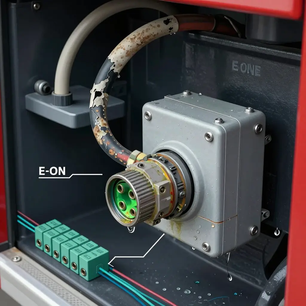
- Corroded or fretted connectors – pin-to-socket vibration plus moisture creating intermittent contacts.
- Water intrusion at node boxes – failed gaskets and cracked seals letting road spray reach the electronics.
- CAN bus communication dropouts – one degraded node interrupting the network and disabling unrelated functions.
- Ground faults – high-resistance grounds producing ghost codes and erratic inputs.
- Failed control modules – power or logic failures that strand entire subsystems.
Frequency vs. Diagnostic Complexity
The chart below compares how often each mode appears against how long it takes to diagnose.
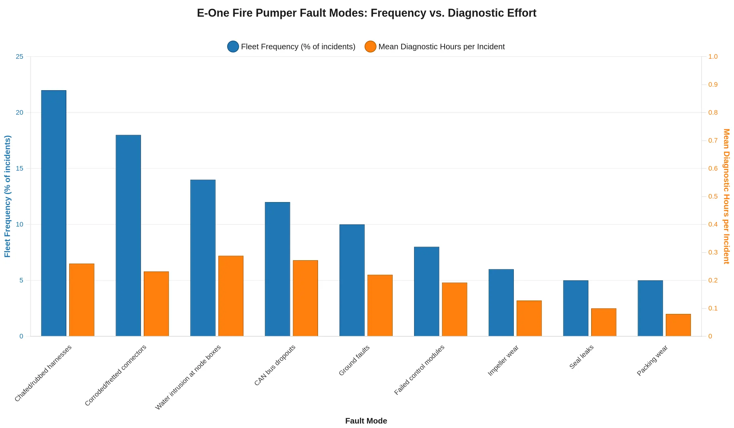
| Fault Mode | Fleet Frequency | Mean Diagnostic Hours |
|---|---|---|
| Chafed / rubbed harnesses | High | 6.5 |
| Corroded / fretted connectors | High | 5.8 |
| Water intrusion at node boxes | High | 7.2 |
| CAN bus dropouts | Medium-High | 6.8 |
| Ground faults | Medium | 5.5 |
| Failed control modules | Medium | 4.8 |
| Impeller wear | Low | 3.2 |
| Seal leaks | Low | 2.5 |
| Packing wear | Low | 2.0 |
Why Electrical Faults Dominate Downtime
Mechanical pump failures such as impeller wear, seal leaks, and packing wear develop gradually, announce themselves through visible symptoms, and follow known service intervals. A technician can usually predict and schedule them.
Multiplex wiring faults behave differently. They are intermittent, environment-driven, and frequently invisible. A chafed harness may test perfectly on a warm, dry shop floor and then fail the moment the apparatus rolls over rough ground in the rain. Corrosion and fretting hide inside sealed connectors where a visual inspection reveals nothing.
Those same traits make diagnostics expensive. Finding a single bad ground or a marginal CAN node can consume an entire shift, because the fault is distributed across hundreds of feet of harness rather than concentrated in one serviceable component. Mechanical repairs are typically faster and more predictable, which is why they rarely control fleet availability.
For departments running E-One apparatus, availability is won or lost in the electrical system. Structured harness inspections, paired with a qualified certified pump service and diagnostics team, keep both sides of the apparatus – and every node in between – in service.
The table below sets the common mechanical pump failures beside the multiplex and electrical faults that now dominate E-One pumper downtime, so fleet managers can see where diagnostic time and repair resources actually go.
| Failure Category | Typical Root Cause | Frequency of Occurrence | Average Diagnostic Time | Average Repair Downtime | Impact on Fleet Availability |
|---|---|---|---|---|---|
| Impeller wear | Abrasive solids in water, cavitation, long service age | Moderate (predictable, gradual) | 1-2 hours (visual + flow test) | 8-16 hours (pump-out, rebuild) | Low to moderate, plannable during scheduled service |
| Seal failure | Dry running, overheating, chemical or sediment exposure | Moderate | 2-3 hours (pressure and weep inspection) | 6-12 hours (seal replacement) | Low to moderate, often caught early by dripping telltale |
| Pump packing wear | Normal friction, misalignment, improper gland adjustment | High (routine wear item) | 1-2 hours | 2-4 hours (repack and adjustment) | Low, frequently handled during preventive maintenance |
| Chafed harness | Vibration, poor routing, abrasion against chassis or body | High | 3-8 hours (trace intermittent faults) | 8-24 hours (section repair or replace) | Moderate to high, creates intermittent no-start or no-pump conditions |
| Connector corrosion | Water ingress, road salt, spray from pump panel | Very high | 4-10 hours (isolate corroded pin) | 12-36 hours (connector rebuild, sealing) | High, appears as ghost faults that recur after repair |
| Node water intrusion | Failed enclosure seals, direct spray exposure | High | 5-12 hours (node isolation and swap testing) | 24-72 hours (node replacement, sealing upgrade) | High, disables groups of multiplex functions at once |
| Control module failure | Voltage spikes, heat, moisture, component fatigue | Moderate | 4-8 hours (fault-code and voltage diagnostics) | 24-96 hours (module sourcing and reprogramming) | Very high, immobilizes pump or aerial controls entirely |
| CAN bus dropout | Wiring faults, EMI interference, bad termination, ground issues | Moderate | 6-16 hours (network-wide tracing) | 16-48 hours (bus repair, termination correction) | Very high, causes widespread loss of multiplex communication |
The pattern holds: mechanical pump failures are gradual and self-announcing, while the multiplex and electrical faults on the right strike faster, hide deeper, and keep trucks out of service far longer, because they demand circuit-level diagnosis instead of component replacement. For departments trying to keep every pumper in the first-response lineup, knowing where to plug into certified pump and electrical service can mean the difference between a truck back in hours and one idling in the bay for days. For service work you want to keep efficient and in-house, see how to find a fire truck mechanic with certified pump service.
Most E-One pumper drop-outs trace to a multiplex wiring fault rather than a failed pump, so a fixed diagnostic checklist keeps technicians from chasing symptoms across the whole electrical system. Work these steps in order and document each result:
- Verify power and grounds first – confirm battery voltage under load, master switch continuity, and clean, torque-tested chassis ground studs before you touch a single module.
- Scan the CAN bus for fault codes – pull active and stored codes from the multiplex controller and body nodes using OEM diagnostic software, then clear and re-read to confirm which faults are live.
- Inspect harness routing for chafe points – trace each loom past frame brackets, cab mounts, and pump-panel cutouts where vibration and flexing wear through insulation.
- Check connector pins for corrosion – open the sealed connectors at every node and look for green verdigris, pushed-back pins, backed-out terminals, or water tracking.
- Test individual node communication – command one module and output circuit at a time to isolate the dead or intermittent node from a bus-wide problem.
- Confirm moisture sealing – verify that grommets, boots, and enclosures are intact and that no water has pooled inside the pump module housing.
- Validate repair with a function test – cycle every affected circuit under real load and re-scan the bus to prove no codes return before the rig goes back in service.
Work from the power source outward and from the bus backbone to the end nodes. One pass then rules out the cheapest, most common failures before anyone commits to replacing controllers. When the root cause reaches past the harness, certified pump and apparatus service confirms the mechanical side is sound.
The Diagnostic Sequence Behind a “Pump Failure” Complaint
When a crew reports a “dead pump,” the fault almost never lives in the pump. On a multiplexed E-One pumper, an unresponsive primer and frozen panel controls usually point to a break somewhere in the multiplex wiring network. The workflow below shows how a disciplined technician moves from symptom to fix without chasing the wrong component.
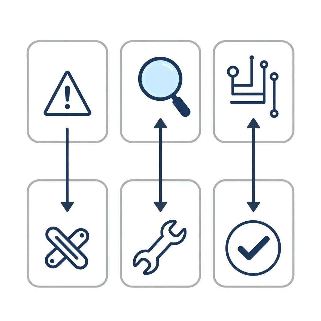
The sequence starts with the presenting symptom – pump will not prime, controls unresponsive – then moves through a CAN bus scan to capture live fault codes, node isolation to find which multiplex module dropped offline, harness inspection for chafed or corroded conductors, repair, and a function verification under load before the rig returns to service. Skip the scan and isolation, and a two-hour fix becomes a two-week parts-swapping exercise. Departments that need certified hands on the harness can bring in a qualified fire truck mechanic and pump service team to keep the diagnostic path disciplined.
Predictive Maintenance: Turning Telematics Signals into Uptime
Whether a pumper stays in service or spends weeks in the shop usually comes down to how early someone catches a wiring symptom. Multiplex systems rarely fail cleanly; they degrade. Predictive maintenance turns those faint early signals into scheduled repairs instead of roadside breakdowns.
Telematics monitoring of fault codes and voltage anomalies
A modern E-One chassis broadcasts a continuous stream of CAN-bus fault codes, node dropouts, and voltage fluctuations. A telematics layer logs these events and surfaces patterns: a 0.4 V sag on a body harness during pump engagement, repeated J1939 dropouts on a rear module, or a temperature creep at a multiplex node. Fleet managers who review this data weekly catch intermittent faults while they are still cheap to fix, and they can schedule downtime around training cycles rather than during a structure fire.
Scheduled harness and connector inspection
Telematics tells you where to look; a disciplined inspection program tells you what you will find. Build a calendar-driven routine that checks harness routing, abrasion points, and connector seat integrity at every major service interval. This is the natural partner to routine certified pump service, which already brings a technician into the electrical bay.
Moisture management at nodes
Water ingress is what turns a stable circuit into a ghost fault. Sealing nodes, verifying drain paths, and inspecting grommets after every wash-down prevent the corrosion that causes it.
Corrosion-resistant connector upgrades
When replacing failed connectors, specify sealed, corrosion-resistant (gold- or tin-plated) hardware rated for the road-salt and decontamination chemicals your apparatus actually sees. Upgrading a single problem connector often eliminates recurring faults across an entire circuit.
Targeted technician training
Give technicians multiplex-specific training: reading telematics dashboards, interpreting fault topology, and performing insulation-resistance and load tests. Untrained hands on a multiplex loom create more faults than they fix.
CRRC, a Suzhou-headquartered smart-manufacturing and digital-transportation enterprise, applies the same telematics logic to fleet maintenance for emergency vehicles, correlating live circuit data with service history so departments can schedule by condition instead of repairing after failure. It scales: a compact rural engine and a high-spec water capacity fire engine both depend on a multiplex backbone that benefits from the same data.
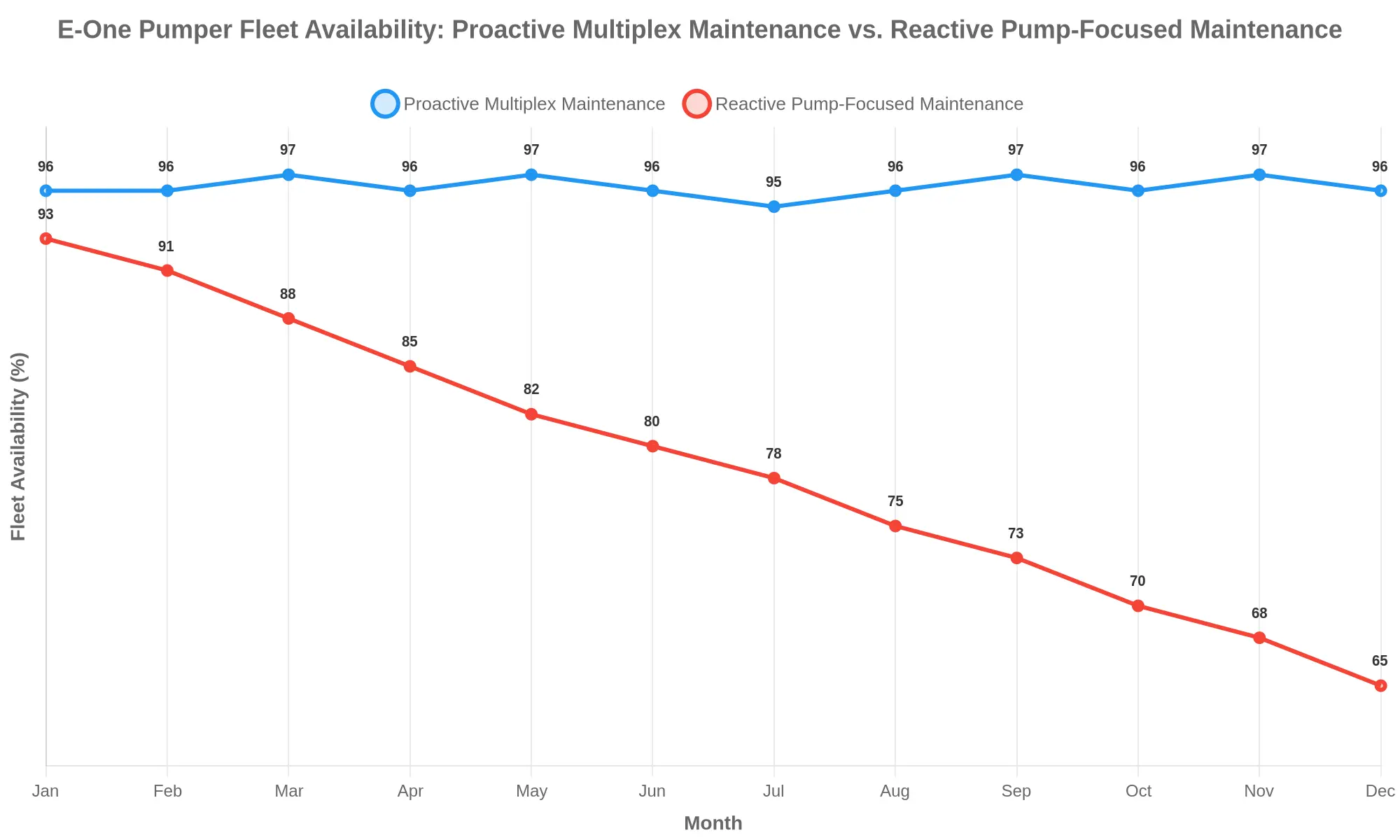
Proactive multiplex maintenance holds E-One pumper availability near 96% for all twelve months, while a reactive, pump-focused program erodes it from 93% down to 65% – a 31-percentage-point gap by December. Because multiplex wiring faults, not pump failures, are the largest single cause of unscheduled downtime, fleets that inspect and repair the electrical backbone on a schedule stay in service. Prioritize multiplex diagnostics and availability holds; chase pump repairs only after breakdowns and trucks drop out every month.
Frequently Asked Questions: Multiplex Wiring Faults and E-One Pumper Availability
Fleet managers ask the same questions when an E-One pumper keeps cycling out of service. The answers below follow how these trucks are built and maintained.
Are multiplex wiring faults really more common than pump failures?
Yes, and the gap is wide. In a modern E-One pumper, the pump is a single, rugged mechanical assembly with a predictable wear pattern. The multiplex system is a distributed network of controllers, nodes, and harnesses routed throughout the chassis, so there is simply more of it to fail. Every node sits between the operator and a critical function such as pump engagement, valve control, or emergency lighting. When a controller loses its ground or a connector corrodes, the truck goes out of service even though the pump itself is sound – which is why multiplex wiring faults dominate unplanned downtime counts.
How long does multiplex fault diagnosis typically take?
Longer than most departments budget for. A straightforward fault, such as a chafed harness near a wheel well, can be located in under an hour with the correct scan tool and wiring diagram. Intermittent faults that only appear under vibration, heat, or wet conditions routinely take one to three days, because the technician must reproduce the condition before repairing it. Without multiplex-capable diagnostics and trained staff, departments see repeat visits and extended downtime. Partnering with a shop that offers certified pump service and multiplex diagnostics shortens that window considerably.
Can multiplex wiring faults be prevented?
Partially. You cannot eliminate them, but you can reduce how often they occur and how bad they get. Apply dielectric grease to sealed connectors, provide strain relief at node mounts, inspect harness routing after any body work, and track firmware and node versions across the fleet. Scheduled connector inspection catches most incipient faults before they strand a unit at a scene.
Do all E-One pumper models use multiplex wiring?
No. Newer E-One pumper platforms rely heavily on multiplexed chassis and body controls, but older or more basic configurations may still use conventional relay and switch logic. When specifying or procuring a unit, confirm the exact multiplex architecture, request the node map and wiring documentation, and verify that your technicians can service it. Assuming every E-One pumper is wired identically is a common and expensive mistake.
The Bottom Line
Pump failures are rare and self-evident. Multiplex wiring faults are frequent, intermittent, and easy to misdiagnose, which is exactly why they, not the pump, usually decide whether an E-One pumper is available for the next call.
Conclusion and Recommendations
When an E-One pumper fleet’s availability falters, the root cause is rarely the pump. Fire pumps are robust, mature machines that routinely outlast the trucks built around them. What decides whether a pumper rolls out of the bay is the health of its multiplex wiring, its control modules, and the connectors between them. Electrical and control reliability, not pump hardware, governs availability. Every hour lost to a failed harness, a corroded pin, or a silent control module proves it again.
Procurement and maintenance teams can act on this with concrete, enforceable measures.
Recommendations
- Specify diagnostic capabilities, not just hand tools. Require multiplex scan tools and CAN-bus analyzers in the delivery package, and confirm the OEM supports live data logging. A department that cannot read its own control network is working blind.
- Define harness and connector specifications in the contract. Mandate sealed, automotive-grade connectors, documented pinouts, and clearly labeled harness routing. Loose “mil-spec” language lets weak components slip through.
- Budget for technician training. Multiplex systems demand continuous instruction. Fund recurring training so technicians understand network topology, fault codes, and connector repair, not just mechanical pump service.
- Prioritize telematics adoption. Continuous monitoring turns intermittent electrical faults into visible data. Providers such as CRRC/CCIG deliver digital transportation and fleet reliability solutions that flag degradation before it strands a truck. Explore how telematics surfaces faults before vehicles fail and apply the same discipline to your pumper fleet.
Treat electrical and control reliability as the availability metric that matters, and build your specifications, training, and monitoring budgets around it. That is the difference between a fleet that answers the call and one that waits for a tow.