

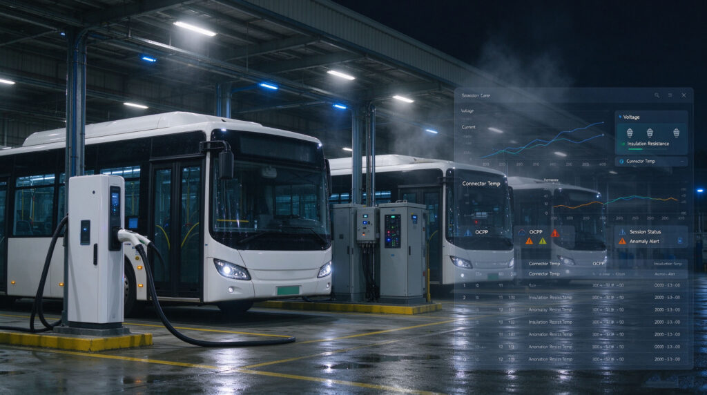
How Electric Bus Telematics Captures Charge Point Data
A charging session is a quiet stream of measurements. Every second, the charger and the bus exchange numbers that describe how safely and efficiently power is moving. Electric bus telematics is the layer that turns those numbers into something a fleet manager can act on. Here is where the data is created, how it is stamped and formatted, and how it reaches a fleet management dashboard.
Where the signals are created
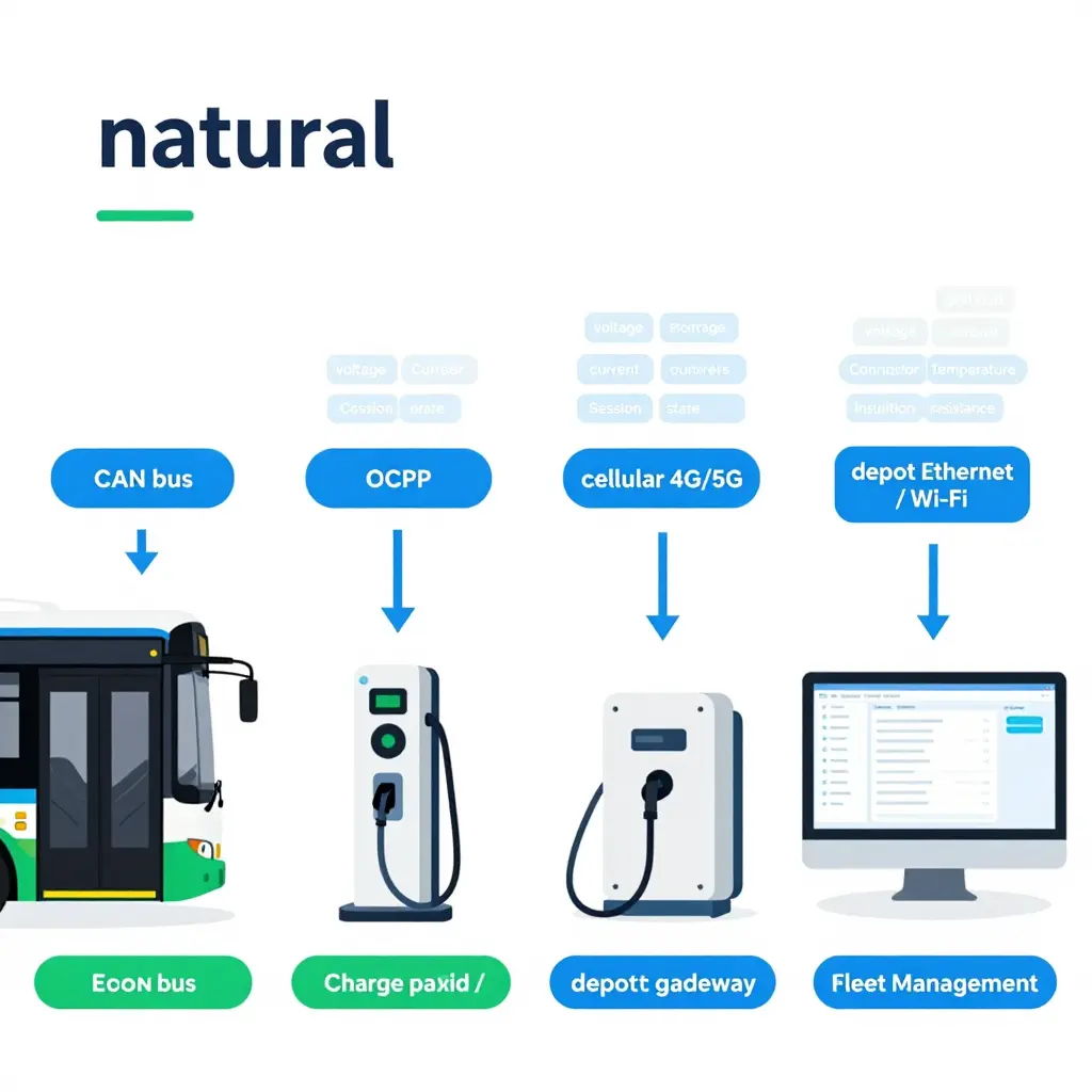
Data is generated in two places at once. The charge point – the physical piece of your charging infrastructure – measures what is happening on the cable, while the bus measures what is happening on board. A telematics control unit (TCU) sits on the vehicle and reads the bus’s internal network through the CAN bus, the same wiring that carries messages between the battery management system, the drivetrain and the charger interface.
The charger’s own controller produces its readings independently. It knows the voltage and current it is delivering, the state of each session, and any fault it has detected. One source alone gives a partial view; together they cover the whole session.
The main data categories
Here is what actually gets captured and reported:
- Voltage – AC input and DC output levels, so operators can spot sag, spikes or an unstable supply.
- Current – how many amps flow during each phase of a charging session.
- Session state – plugged in, handshaking, charging, suspended, faulted or complete.
- Error codes – OCPP fault codes that name the exact fault instead of a vague “something went wrong”.
- Connector temperature – heat at the plug, one of the earliest warnings of a degrading connection.
- Insulation resistance – a safety check confirming the high-voltage circuit is properly isolated.
- Grid load – the demand a site places on the local supply, useful for avoiding peaks.
Timestamping and formatting
Each reading is time-stamped the moment it is captured, usually against a synchronised clock, so events from different devices line up correctly. The charger’s controller then packages its messages in OCPP, the Open Charge Point Protocol, which defines exactly what a status update, a meter value or a fault notification should look like. This shared vocabulary is why a dashboard can compare a fault on one charger with a fault on another and know they mean the same thing.
The journey to the dashboard
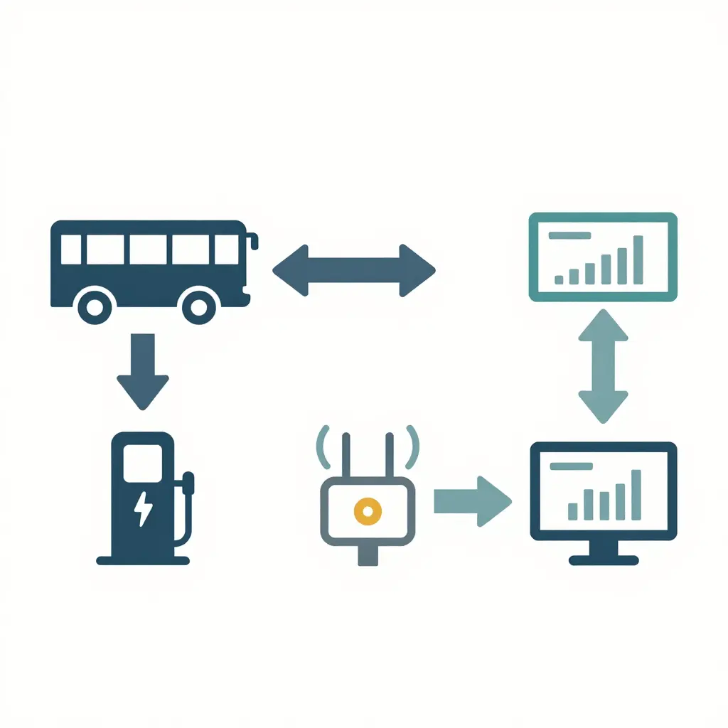
From the vehicle and the charger, data flows toward a depot gateway – an on-site concentrator that collects signals from many charge points at once. The gateway forwards everything to the fleet management dashboard, where it is stored, charted and used to trigger alerts.
The path uses a mix of networks. Inside the depot, gateways often rely on wired Ethernet or a local wireless network. On the road, telematics control units use cellular links to stay connected. Getting that mix right is part of planning reliable depot power upgrades so that charging and reporting never compete for the same weak connection.
Why integration standards matter
Systems built for public transport have to hold up for years, not months. CCIG – the Suzhou-based, state-owned mixed-reform group behind these digital transportation solutions – works to that expectation. In practice it favours open, documented protocols over closed ones, tests compatibility between chargers and vehicles before deployment, and designs a Charge Point Management System (CPMS) that keeps working when a single link drops.
Capture every signal – from connector temperature to a single OCPP fault code – time-stamp it, and carry it through a chain you understand, and most faults are caught before a driver ever picks up the phone to report one.
The Most Common Charge Point Faults in Electric Bus Fleets
Charge point faults rarely announce themselves. In most depots they build slowly, leaving faint traces in electric bus telematics weeks before a charger finally refuses a session. Knowing the main fault families, and the data each one leaves behind, is what turns reactive repair into planned maintenance.
Ground and Insulation Faults
Insulation resistance tends to drift downward as cables age, connectors collect moisture, or conduit absorbs water. The charger’s leakage current readings creep upward while sessions still complete. Nothing fails outright, so the drift sits quietly in the logs until a damp morning pushes resistance past the trip threshold and the unit simply will not start.
Connector, CCS Pin, and Cable Faults
Bent pilot pins, worn CCS (Combined Charging System) contacts, and crushed cables cause intermittent handshakes. Telematics shows repeated connect and disconnect loops, sessions that begin then abort within seconds, or a slowly rising contact resistance. Drivers often assume their own plugging technique is at fault, so the issue circulates for weeks before anyone ties it to one connector.
Over-Temperature and Derating Events
Heat builds when contacts carry high current with poor mating, when cooling paths clog, or when ambient temperatures spike. The charger derates, delivering less power than requested. In telematics this appears as a widening gap between requested and delivered current. It goes unnoticed because the bus still charges, just more slowly, and the reduced rate only bites when schedules tighten.
Communication and OCPP Handshake Failures
Firmware mismatches, network dropouts, and certificate or configuration errors interrupt the Open Charge Point Protocol conversation between charger and backend. The data shows failed or retried handshakes, missing session records, and gaps in the charge log. These faults hide behind occasional “charger offline” notices that staff dismiss as ordinary network hiccups.
Protective-Earth and RCD Trips
Degraded earthing or moisture ingress can trip a residual current device (RCD), cutting a session mid-charge. Telematics captures abrupt session endings with no driver-initiated stop, clustered on a single unit. A reset clears it and the charger runs again, so a recurring fault reads as a random glitch rather than a failing installation. Whether the root cause is a degraded connector or broader depot power constraints, the earliest warning usually lives in the data.
Meter and Power Discrepancies
Metering drift, calibration errors, or mismatched current transformers create a gap between the energy a charger reports and the energy a vehicle records. The discrepancy grows gradually. Finance teams often query billing long before maintenance sees a fault, since no safety limit is breached and charging continues normally.
Why These Faults Slip Through
Every category behaves the same way: the fault leaks signals long before it causes a failed session. A small leak here, a mild derate there, an aborted handshake that retries successfully. Individually these events look harmless. Trended across a fleet, they form a clear signature.
| Fault category | Typical cause | Telematics signature | Why it hides |
|---|---|---|---|
| Ground and insulation | Aged cables, moisture ingress | Rising leakage current | Sessions still complete |
| Connector and CCS pins | Bent pins, worn contacts | Connect/disconnect loops | Blamed on plugging technique |
| Over-temperature | Poor mating, clogged cooling | Growing requested vs delivered gap | Bus still charges slowly |
| Communication and OCPP | Firmware and network errors | Failed handshakes, log gaps | Dismissed as network hiccups |
| Protective-earth and RCD | Degraded earthing, moisture | Abrupt sessions with no stop command | Trip resets itself |
| Meter discrepancies | Metering drift, CT mismatch | Charger vs vehicle energy gap | Charging continues normally |
The value for fleet managers is in watching the trend rather than the alarm. A single derate or one aborted handshake means little on its own, but a rising baseline across a fleet points straight to the unit that needs attention next – turning charge point faults into planned work instead of morning surprises.
Fault Type vs. Telematics Detection Signal vs. Lead Time Before Driver Report
Diagnosing electric bus charge point faults gets much easier once you know which signals to watch and how much warning they give you. The table below maps the six most common fault categories to their early-warning telematics signals, so your team can act before a driver ever files a report.
| Fault Type | Typical Symptom | Telematics Detection Signal | Approximate Lead Time Before Failure | Which Data Source Flags It |
|---|---|---|---|---|
| Ground / insulation fault | Aborted or intermittent charging sessions | Rising leakage current, insulation resistance drop | Days to weeks | Charger + CPMS |
| Connector fault | Slow charging, repeated plug retries | Abnormal contact temperature, pin voltage drop | Hours to days | Charger + Vehicle |
| Over-temperature derating | Reduced charge power, longer sessions | Rising cell/module temperature, BMS current limit | Minutes to hours | Vehicle + CPMS |
| Communication handshake failure | Charger will not start a session | Repeated failed handshakes, connection timeouts | Real time to hours | CPMS + Charger |
| RCD trip | Charger shuts down, no power delivered | Earth leakage trip event, sudden session cut-off | Immediate to hours | Charger |
| Metering discrepancy | Incorrect billing, energy disputes | Delivered energy mismatch between meters | Days to weeks | CPMS + Vehicle |
Knowing which data source – the vehicle, the charger, or the CPMS – raises each flag is what turns raw telematics into a workable maintenance plan. Teams that pair this map with robust depot power infrastructure can schedule repairs during off-peak windows instead of reacting to roadside breakdowns.
From Reactive to Proactive: Catching Charge Point Faults Early
The most expensive charge point fault is the one a driver discovers at 5 a.m. with a full passenger load already waiting. Reactive maintenance treats every failure as a surprise: a session dies, a bus misses its block, and a technician scrambles to diagnose a problem that has been quietly developing for weeks. Electric bus telematics flips that logic on its head. Instead of waiting for a breakdown report, continuous monitoring watches every session in real time and asks a sharper question: is this charge point still behaving the way it should?
The logic behind proactive fault detection
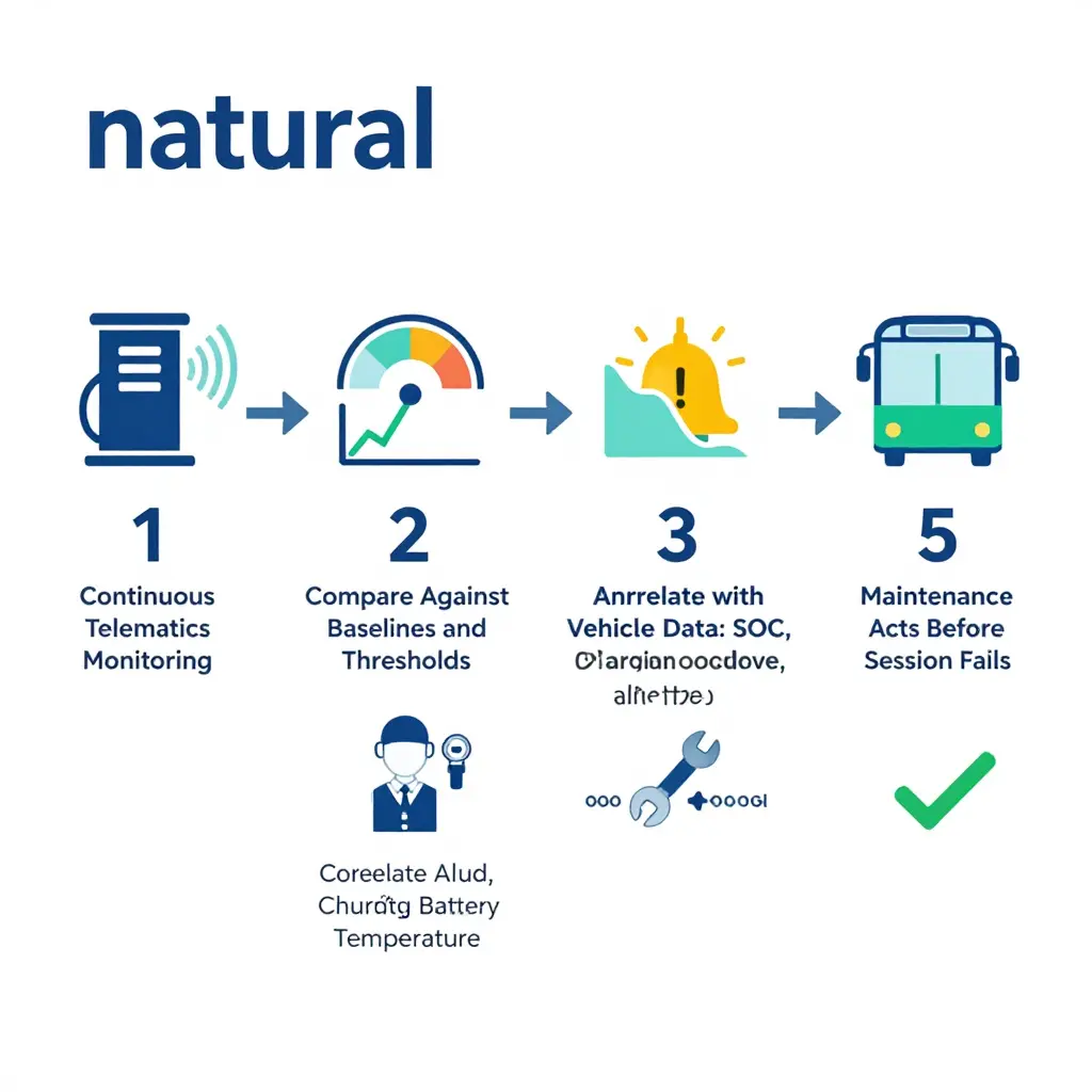
At its core, proactive detection is a comparison engine. Telematics streams hundreds of signals from each charger – output current and voltage, connector temperature, handshake timing, power ramp rates, and session start/stop events. The platform measures those live values against two reference points:
- Baselines, the normal signature of that specific charge point across hundreds of healthy sessions.
- Thresholds, hard engineering limits beyond which safe or reliable operation can no longer be guaranteed.
When live behaviour drifts from the baseline, or crosses a threshold, the system does not simply record it – it flags it. Rule-based alerts catch obvious breaches, while anomaly detection models catch subtler patterns: a connector running a degree or two hotter each week, a power ramp that takes a few seconds longer every month, an error code that appears once, then twice. These are the fingerprints of degradation, and they surface long before a session outright fails. That early warning is the entire point – it gives maintenance teams a window to intervene on their own schedule rather than the charger’s.
Descriptive versus predictive alerting
It helps to separate two layers of monitoring. Descriptive monitoring answers what happened: dashboards and logs that document completed sessions, energy delivered, and past faults. It is essential for reporting, but it is inherently backward-looking. Predictive alerting answers what is about to happen. By trending degradation signals against expected behaviour, it forecasts the probability that a charge point will fail within a defined horizon and recommends action. One tells you the story after the fact; the other gives you a chance to change the ending.
Cutting false positives with vehicle-side data
A lone charge point alert is ambiguous. Is the charger degrading, or is the bus the real source of the problem? This is where correlating charge point telematics with vehicle-side data transforms diagnosis. By pairing charger signals with the vehicle’s state of charge, charging curve, and battery temperature, the platform distinguishes a genuine charge point fault from normal vehicle-side behaviour such as a battery tapering its acceptance rate as it fills. The result is fewer false positives, faster root-cause identification, and maintenance that targets the right asset instead of chasing phantom faults.
Why this matters for the wider depot
Proactive monitoring also reframes how fleets think about infrastructure limits. When depot power is marginal or shared across too many vehicles, chargers do not always fail outright – they degrade, slow down, and produce erratic sessions that masquerade as equipment faults. Recognising these signatures is central to understanding why electric bus fleets stall when depot power is underestimated, because many apparent charge point faults are really symptoms of an underpowered or poorly balanced depot rather than a broken unit.
Why the shift pays off
Predictive maintenance for charging infrastructure is not a luxury add-on; it is the difference between firefighting and planning. By continuously benchmarking live charge point behaviour, flagging degradation through anomaly detection and rule-based alerts, and cross-checking every alert against vehicle-side data, electric bus telematics turns charge point faults from unpleasant surprises into managed, foreseen events. Fleet managers who make that shift stop reacting to failures and start preventing them.
The Shift From Reactive to Proactive Fault Detection
This line chart plots detection lead time (measured in hours before an actual failure) across a twelve-month period. The red line shows what happens when faults are caught only after a driver reports them, while the green line shows the same fleet once telematics continuously monitors charge point health.
The takeaway for fleet managers is stark. Reactive reporting hovers in the single digits all year, giving maintenance teams almost no runway. Telematics-driven detection climbs to more than 70 hours of early warning, turning emergency breakdowns into scheduled repairs. For a deeper look at how depot infrastructure can hold a fleet back from this level of resilience, explore why electric bus fleets stall at the depot.
Key Signals and Metrics to Monitor on Every Charge Point
Effective electric bus telematics is not about collecting the most data – it is about surfacing the handful of signals that expose developing charge point faults before a driver ever reports a problem. Alongside sensible depot power upgrades that keep fleets from stalling, the metrics below should be visible on every charge point dashboard across your charging infrastructure.
- Session success and failure rate – The share of initiated sessions that complete cleanly is the single most honest indicator of charger health. A downward trend in success rate typically precedes hard failures, signalling intermittent handshake problems or connector wear long before a full outage appears.
- Charger availability and uptime – Availability measures the percentage of time a unit is ready to dispense power, while uptime measures whether it actually does. Falling availability while uptime still looks healthy usually points to units idling in fault states that never reach the driver-facing screen.
- Connector temperature and pin resistance trends – Rising connector temperatures or creeping pin resistance indicate worn contacts, poor seating, or corrosion building inside the plug. Because these changes are gradual, a trend line catches overheating risk that any single reading would miss.
- Insulation resistance values – This measures how well the charging cable and connector isolate live conductors from earth. A steady downward drift is an early warning of moisture ingress or cable damage and is a classic precursor to insulation-related charge point faults.
- Number of derating events – Derating is the charger deliberately cutting power to protect itself, and each event is a logged stress signal. A rising count suggests the unit is frequently operating outside its safe envelope, often because of thermal or voltage stress.
- OCPP error and handshake codes – Because the Open Charge Point Protocol drives communication between charger and back office, its error and handshake codes are a diagnostic goldmine. Repeated or novel codes let managers pinpoint fault categories – authentication, communication, or hardware – without dispatching a technician first.
- Energy delivered versus expected – Comparing actual kilowatt-hours delivered against the expected value for a given session length exposes hidden underperformance. A widening gap often means the charger is throttling output or the vehicle battery is limiting acceptance, both worth investigating.
- Start-up voltage anomalies – Spikes or sags in supply voltage at the moment charging begins can trip protection circuits or shorten component life. Trending these anomalies reveals unstable upstream power that no single session would otherwise flag.
To turn this stream of readings into action, fleet managers should adopt a baseline-and-threshold approach. Record a normal operating range for each metric during stable, healthy operation, then set warning and critical thresholds relative to that baseline rather than to arbitrary absolute values. This prevents seasonal swings, weather, and duty-cycle variation from triggering false alarms, so that only meaningful deviations – the genuine early-warning signals – rise to the top. Applied consistently across a fleet, this discipline turns electric bus telematics from a passive logbook into a proactive risk-management tool that protects the reliability of your charging infrastructure.
How to Introduce Telematics-Based Charge Point Monitoring in Your Depot
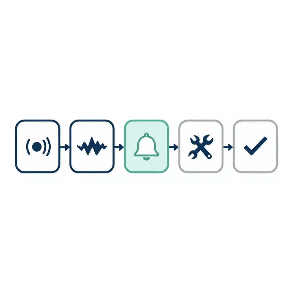
Rolling out electric bus telematics for charge point monitoring does not have to be a single, disruptive project. A staged approach lets fleet managers prove value early, build operator confidence, and refine detection logic before it influences daily dispatch and maintenance planning. The eight steps below offer a practical sequence for standing up a monitoring programme that surfaces charge point faults before drivers notice them on the road.
Inventory and map every charge point. Start by documenting each charger in the depot, including its location, model, power rating, connector type, and the routes or vehicles it typically serves. A shared map links each physical unit to an asset ID, so any anomaly can be traced to a specific bay rather than a vague “depot charger.” This baseline inventory becomes the reference point for every later alert.
Standardise data through OCPP. Adopt the Open Charge Point Protocol so chargers from different vendors report consistent, comparable fields rather than proprietary formats. Standardising on OCPP means session start and stop times, energy delivered, error codes, and status transitions arrive in one common language. Without this normalisation, cross-site comparison and automated detection become impractical.
Define baseline behaviour for each charge point. Establish what normal looks like by logging charging sessions over a representative period before setting any alarms. Record typical power curves, session durations, energy throughput, and connector utilisation for each bay. These baselines let you distinguish genuine charge point faults from expected variation caused by state of charge, weather, or scheduling.
Set alert thresholds and escalation rules. Translate your baselines into concrete thresholds, such as a session that delivers unusually low energy, aborts early, or shows repeated communication dropouts. Define who is notified, how quickly, and what happens if the alert is not acknowledged. Clear escalation rules prevent important signals from being buried and ensure the right technician responds.
Integrate telematics with fleet management and maintenance systems. Connect charging data to your fleet management and computerised maintenance management platforms so faults trigger work orders automatically. Linking vehicle telematics with charger events shows whether a problem sits with the bus, the charger, or the grid supply. This integration removes manual data entry and keeps maintenance history in one place. For operators concerned about accountability, telematics records can also support evidence-based warranty and charging-quality discussions, as explored in this guide to electric bus battery warranty and fast-charging disputes.
Train operations and maintenance staff. Give depot staff, dispatchers, and technicians role-specific training on reading dashboards, interpreting alerts, and escalating issues correctly. Explain what each alert means and the cost of ignoring it, so warnings are treated as actionable rather than background noise. Well-trained teams catch charge point faults faster and reduce unnecessary charger downtime.
Review and tune alerts on a recurring cycle. Schedule regular reviews, for example monthly, to examine false positives, missed faults, and threshold performance against real outcomes. Adjust thresholds and add new detection rules as your fleet, charging patterns, and hardware evolve. Continuous tuning keeps the monitoring system accurate and trusted over time.
Document, report, and improve continuously. Keep a log of incidents, root causes, and resolutions so recurring charge point faults can be addressed at the source rather than patched repeatedly. Share periodic reports with operations, procurement, and maintenance leadership to justify investment and prioritise repairs. Over time, this feedback loop turns raw telematics into a durable reliability advantage.
Following these steps in order gives bus fleet managers a controlled path from raw charger data to proactive fault detection. The payoff is fewer surprise breakdowns, better charger availability, and maintenance decisions grounded in evidence rather than guesswork.
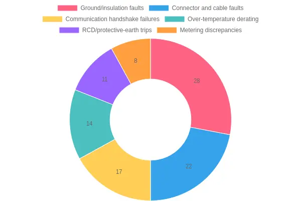
Figure: Share of each major charge point fault category detected over a representative period. Ground and insulation faults dominate, followed by connector and cable faults, with communication handshake failures and over-temperature derating forming a notable second tier.
The Operational and Financial Case for Early Fault Detection
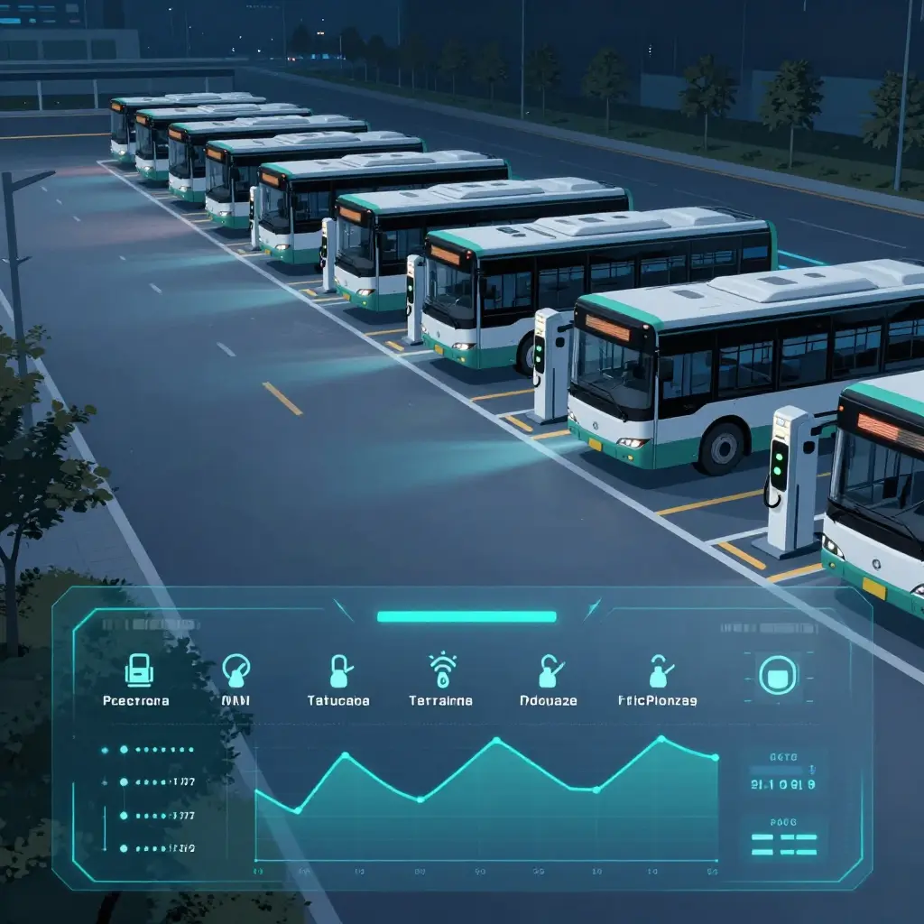
Most depots find out about a charge point fault the hard way: a bus booked for the first departure of the day is still plugged in and barely charged. For fleet managers, that is the most expensive way to learn anything. Reactive maintenance never removes a fault; it only delays awareness until the fault has already cost a departure, a driver’s hours, and the recovery work that squeezes every later trip. Electric bus telematics reverses that order, converting a morning surprise into a scheduled repair.
The Real Cost of Reactive Charging
A defective charge point rarely announces itself. It degrades quietly: intermittent handshakes, reduced output, a connector that works for one bus and faults on the next. Without continuous monitoring, these signals stay invisible until a vehicle fails to charge, and by then the fault has compounded into lost service. Multiply one degraded charger across a depot and the hidden costs stack up fast: last-minute vehicle swaps, overtime for technicians, breakdown call-outs at premium rates, and unplanned loaner hires to cover pulled buses. The expense is not the connector; it is the disruption that late discovery triggers.
The Operational Metrics That Improve
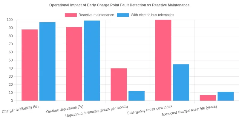
This is where electric bus telematics earns its place. By watching charger handshakes, current output, and error logs in real time, it flags charge point faults while they are still minor and schedulable. The operational picture shifts across several measurable dimensions:
- Higher charger availability. Faults are caught before they take a unit offline, so more chargers are usable during peak plug-in windows.
- Fewer cancelled or delayed departures. Vehicles leave fully charged and on time, protecting published timetables.
- Reduced emergency repair costs. A planned component swap costs a fraction of a 3 a.m. call-out, and early alerts avoid cascading damage to cables and connectors.
- Longer charger and battery asset life. Monitored charging cycles and prompt intervention prevent the thermal and voltage stress that shortens equipment lifespans.
- Better driver and passenger experience. Predictable departures reduce driver frustration and rebuild passenger confidence in reliability.
- Stronger data for warranty and supplier conversations. Timestamped fault histories turn vague disputes into documented evidence, supporting claims and better contract terms.
It is the same principle that applies to any asset: match it to its real workload, then monitor it against that baseline. Telematics applies that logic to charging, continuously.
The Net ROI
Early detection pays back through avoided cost, not added spend. Fewer aborted departures mean more revenue-earning service delivered, while planned repairs replace premium emergency fixes. Higher charger availability lets a depot get more throughput from the equipment it already owns, deferring capital expansion. Longer asset life stretches replacement cycles, and stronger warranty evidence recovers money that reactive fleets simply write off. For fleet managers, the return is not a single number but a compounding one: every fault caught early removes a future delay, a future call-out, and a future dispute. The financial case for electric bus telematics is ultimately a case for trading expensive surprises for cheap certainty.
Frequently Asked Questions About Electric Bus Telematics and Charge Point Faults
What is electric bus telematics?
Electric bus telematics combines onboard sensors, vehicle data networks, and cloud software that continuously collect and transmit operational data from an electric bus. It tracks energy consumption, every charging session, battery health, and component performance in real time, then presents it in a single dashboard view of fleet and charger status. For fleet managers, this data turns raw signals into clear insight about the health of both the vehicles and the charging infrastructure they depend on.
Can telematics really detect charge point faults before a driver reports them?
Yes. Electric bus telematics monitors each charging session at both the vehicle and the charge point, comparing expected voltage, current, and energy delivery against actual values. When readings drift outside normal thresholds, the system raises an alert immediately, often hours before a driver ever encounters a failed charge. That early warning lets teams fix charge point faults during planned downtime instead of during a busy morning departure.
Which charge point faults are hardest to detect?
Intermittent faults are the most difficult, because they often appear only under specific conditions, such as high ambient temperatures or several buses charging at once. Communication errors between charger and vehicle, along with slowly degrading cables and connectors, also hide easily because a single session may still complete successfully. Electric bus telematics catches these patterns by correlating data across many sessions and vehicles over time, surfacing trends that a single charge attempt would miss.
Do I need OCPP-compatible chargers?
OCPP compatibility helps, because the Open Charge Point Protocol standardises how chargers report status and faults. That said, you do not strictly need it, since telematics can often infer charge point faults from vehicle-side data alone. Combining OCPP messages with vehicle telemetry usually delivers the most complete and reliable picture of charger health. If your chargers already support it, activating OCPP data feeds is typically a straightforward configuration step.
How does telematics reduce false alerts?
False alerts usually come from a single sensor catching a momentary spike that resolves on its own. Electric bus telematics reduces them by cross-checking multiple data points, applying time-based thresholds, and confirming anomalies across several charging sessions before sending a notification. This filtering keeps attention on genuine charge point faults and makes predictive maintenance planning more accurate and trustworthy.
Does proactive monitoring help with battery warranty claims?
It can help significantly. Continuous records of charging behaviour, temperature, and state of health give you documented evidence that the battery was operated within the manufacturer’s specified conditions. If a dispute arises over fast charging or capacity loss, this data supports your case with facts instead of assumptions, which is valuable when resolving battery warranty disputes.
How quickly can a depot implement this?
Most depots can be up and running within a few weeks, because the hardware typically installs alongside existing charge management systems without major infrastructure changes. The exact timeline depends on fleet size, charger compatibility, and how much data integration is required. Starting with a small group of buses lets you validate alerts and fine-tune predictive maintenance thresholds before scaling across the whole depot.