

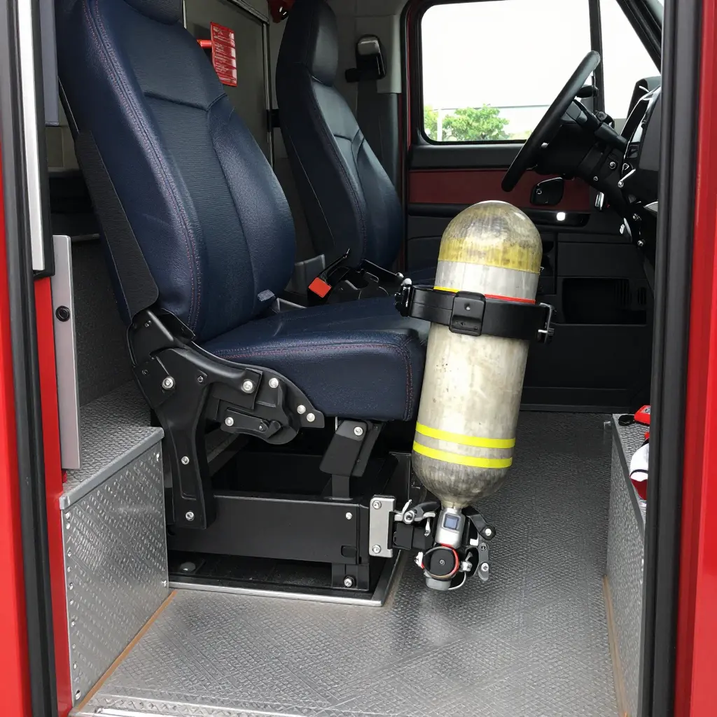
Fire Truck SCBA Seat Brackets: Why Cab Floor Anchorage, Not Seat Count, Decides Crew Restraint Compliance
An SCBA seat bracket is only as compliant as the cab floor it is bolted to. How many seats a cab claims on a specification sheet says nothing about whether the bracket holding a filled cylinder will stay put in a crash. What decides that is where the bracket’s load path enters the floor structure, through what hardware, with what reinforcement, and at what verified strength. A cab can list six SCBA positions and still fail a dynamic restraint test if the anchorage beneath those positions cannot carry the load the bracket transfers into it.
The two ideas get conflated because specifications describe seating in whole numbers and structure in drawings. Bid schedules, comparison matrices and sales literature speak one language (“four seats,” “six SCBA positions,” “NFPA-compliant seating”), while anchorage detail lives in fabrication drawings, reinforcement schedules and test reports that procurement staff rarely see side by side. Write a specification around a seat count and every competing proposal can match that count without ever demonstrating an equivalent load path.
Retrofits compound the problem. Departments replacing aged brackets often specify a replacement by bolt pattern and position count, treating the cab floor as a universal mounting surface rather than a structure with reinforced zones, defined insert locations and documented capacity limits. The bracket matches the hole spacing. Nobody re-verifies the anchorage.
What the Standards Actually Require of SCBA Seat Brackets
Strip the specification-sheet language out of NFPA 1901 and the logic is blunt: the occupant has to stay in the cab, and the equipment mounted beside the occupant has to stay with it. Seating, occupant restraint and SCBA brackets are evaluated as one system, not as three line items.
NFPA 1901 approaches that as a load path rather than a component list. Each riding position has to be designed for the crew member who will occupy it, fitted with a restraint appropriate to that position, and surrounded by equipment that stays in place under crash-level deceleration. At an SCBA seat, the bracket is part of the occupant-protection envelope: a cylinder that breaks free becomes a projectile aimed at the crew it was installed to support.
A compliant seating position is therefore an assembly whose seat anchorage and mounted equipment are engineered, tested and documented as one verified load path into the vehicle structure, and the documentation is what makes the claim checkable.
The Seat as a Counted Item Versus the Seat as a Validated Installation
Counting seats takes minutes. Each one comes with a model number, a listed capacity and a line on the specification sheet, and a purchaser can tally those lines against the crew size on the requisition. None of it says how the assembly behaves when the truck decelerates.
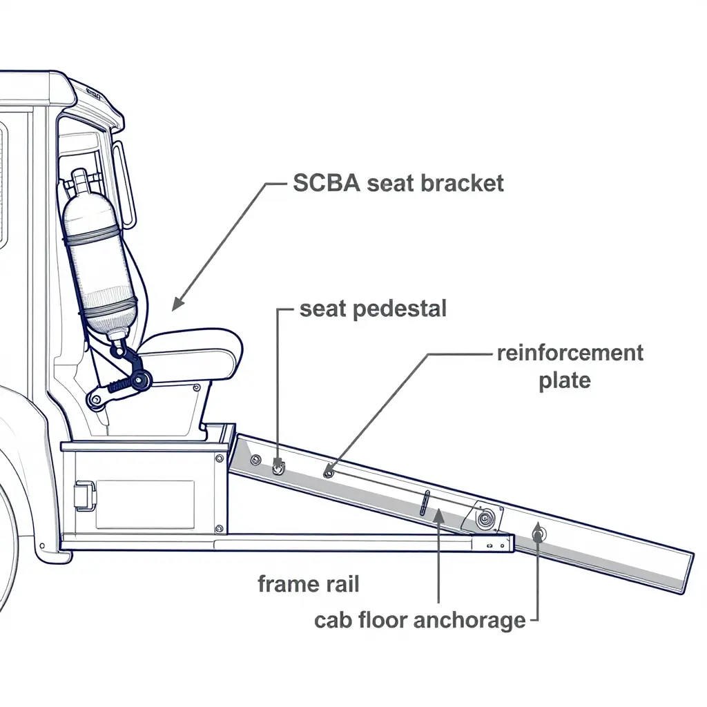
A validated installation is a different kind of object. Its cab floor anchorage (the reinforcement plates, backing structure and fastener schedule that transfer restraint and bracket loads into the frame) is what carries the load, and the documentation is what proves the transfer was engineered rather than assumed.
What an Inspector Can Actually Verify
NFPA 1911 inspection work is built on evidence, because nobody can re-run a dynamic test in the station bay. What an inspector can check is the hardware and the paperwork behind it: anchorage drawings, fastener grades and torque values, reinforcement details, engineering sign-off, and whether the bracket on the truck matches the documented configuration.
A seat tally cannot be checked that way. It records an intention; the anchorage file records a result. When a compliance officer asks how a particular bracket is retained, the answer that holds up is a load path with a calculation and a bolt pattern behind it.
Why This Matters for Crew Restraint Compliance
Two trucks can advertise the same number of riding positions and protect their crews very differently, and the gap only shows up when somebody asks for the engineering record. Buying on seat count alone moves the risk from the specification meeting to the cab floor.
Fleets specifying apparatus on validated municipal vehicle platforms should require that documentation as a deliverable, not count on it as a courtesy.
Specification Comparison: Seat Count vs. Cab Floor Anchorage
The table turns the argument into a side-by-side view. Each row is a question a reviewer, inspector or procurement officer will eventually ask; the two columns show what each approach can answer at design review and after delivery.
Table: Seat Count Approach vs. Cab Floor Anchorage Approach to SCBA Bracket Compliance
| Evaluation Criterion | Seat Count Approach | Cab Floor Anchorage Approach |
|---|---|---|
| What is measured | Number of seating positions recorded in the cab configuration list. | Load path capacity of floor anchorage points under restraint forces. |
| Documentary evidence produced | Seating capacity stated on the sales specification sheet only. | Anchorage calculations, fastener schedules, and test documentation for each bracket. |
| Verifiability during inspection | Inspectors cannot confirm restraint performance from a seat count number. | Inspectors can physically trace brackets, fasteners, and floor plates. |
| Treatment of aftermarket bracket retrofits | Retrofit brackets classified by seat position count, not attachment detail. | Each retrofit requires documented floor anchorage evaluation before installation. |
| Handling of mixed or replaced seating | Mixed seating defeats a simple count and leaves the position ambiguous. | Anchorage review applies uniformly regardless of seat make or age. |
| Response to dynamic loading questions | Seat count offers no answer to crash load or acceleration questions. | Anchorage data answers restraint load questions with calculated capacities. |
| Effect on procurement sign-off | Sign-off rests on specification text reviewed at the quotation stage. | Sign-off requires anchorage evidence reviewed before release to production. |
| Residual compliance risk | Risk stays hidden because seat count cannot reveal weak mounting. | Residual risk is quantified and documented per anchorage location. |
| Primary failure mode | Weak floor mounting goes undetected behind an acceptable seat count. | Undersized or missing anchorage is identified and corrected early. |
| Scope of engineering review | Review limited to layout planning and cab interior space allocation. | Review covers structural attachment, fastener grade, and load distribution. |
| Position after vehicle modification | Any seating change forces requalification of the count, not the mount. | Anchorage remains the controlling reference throughout vehicle service life. |
Seat count produces paperwork. Anchorage produces evidence. Compliance follows the load path, and the load path ends at the cab floor.
Why Seat Count Is a Misleading Compliance Metric
- A counted seat may sit on a floor pan that was never analysed for the added bracket load, so the number describes what is bolted down rather than what the structure was engineered to carry.
- Retrofits can add seats without adding anchorage capacity, because the original floor evaluation was scoped to the layout that existed when the cab was built.
- Seat replacement can invalidate an installation, since anchorage approvals are generally tied to a specific seat model, pedestal and fastener set rather than to a position in the cab.
- A tally carries no information about fastener grade, plate size or substrate thickness, and it cannot tell a bracket tied into structural cross members from one fastened through thin sheet metal. Those variables govern the strength of the load path, and the two arrangements behave very differently under deceleration.
- Counts do not record corrosion, fatigue cracking, elongated holes or previous repairs, any of which can reduce a bracket to cosmetic hardware long before the headline number changes.
- A count says nothing about documentation: no engineering sign-off, no torque and fastener records, and no evidence that the assembly satisfies the seating and occupant restraint provisions in NFPA 1901.
- Counts do not track configuration drift. A cab that gains, loses or swaps brackets between builds still reports the same tally.
Counting items produces an inventory, and an inventory answers one question: how many are there. Tracing load paths produces an engineering conclusion, which answers what safety officers and regulators actually care about: whether each position can put restraint forces into structure without overloading the anchorage, the bracket or the fasteners. Seat count and crew restraint compliance are different measurements, and either can change without the other.
A defensible review therefore starts at the cab floor anchorage. Ask for the load path drawing, the bracket qualification basis, the fastener and plate specification, the substrate thickness at each mounting point, and the inspection record for the hardware currently installed. Buyers evaluating complete municipal vehicle platforms can put that documentation in the specification as a line item, which moves the discussion from how many seats a cab claims to how each bracket proves it belongs there.
Where the Restraint Load Actually Goes
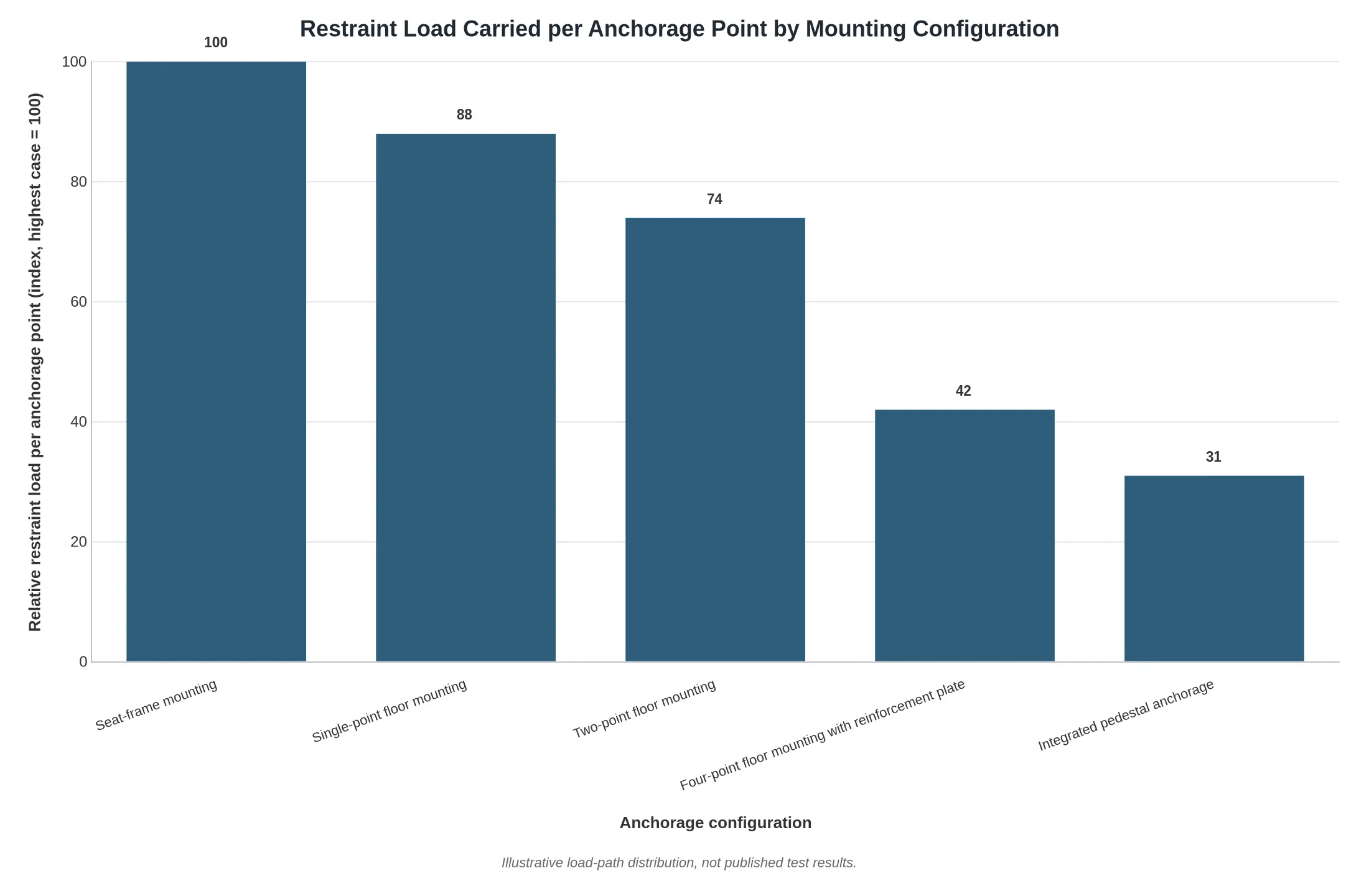
A crew seat is only as compliant as the path its crash loads take into the chassis. The chart indexes the relative restraint load carried by each individual anchorage point across five common mounting arrangements, normalised so the highest-demand case reads as 100.
| Anchorage configuration | Relative load per anchorage point (index) |
|---|---|
| Seat-frame mounting | 100 |
| Single-point floor mounting | 88 |
| Two-point floor mounting | 74 |
| Four-point floor mounting with reinforcement plate | 42 |
| Integrated pedestal anchorage | 31 |
Data note: the plotted values are illustrative of load-path distribution rather than published test results.
Figure 1. Each additional floor-anchored point spreads the peak restraint load, so demand on any single fastener drops: the index falls from 100 on a seat-frame tie to roughly 31 on an integrated pedestal. That is why anchorage governs compliance and seat count does not. What matters is how many load paths tie the seating assembly into the chassis, not how many seats sit on top of it.
The Engineering Logic of Cab Floor Anchorage
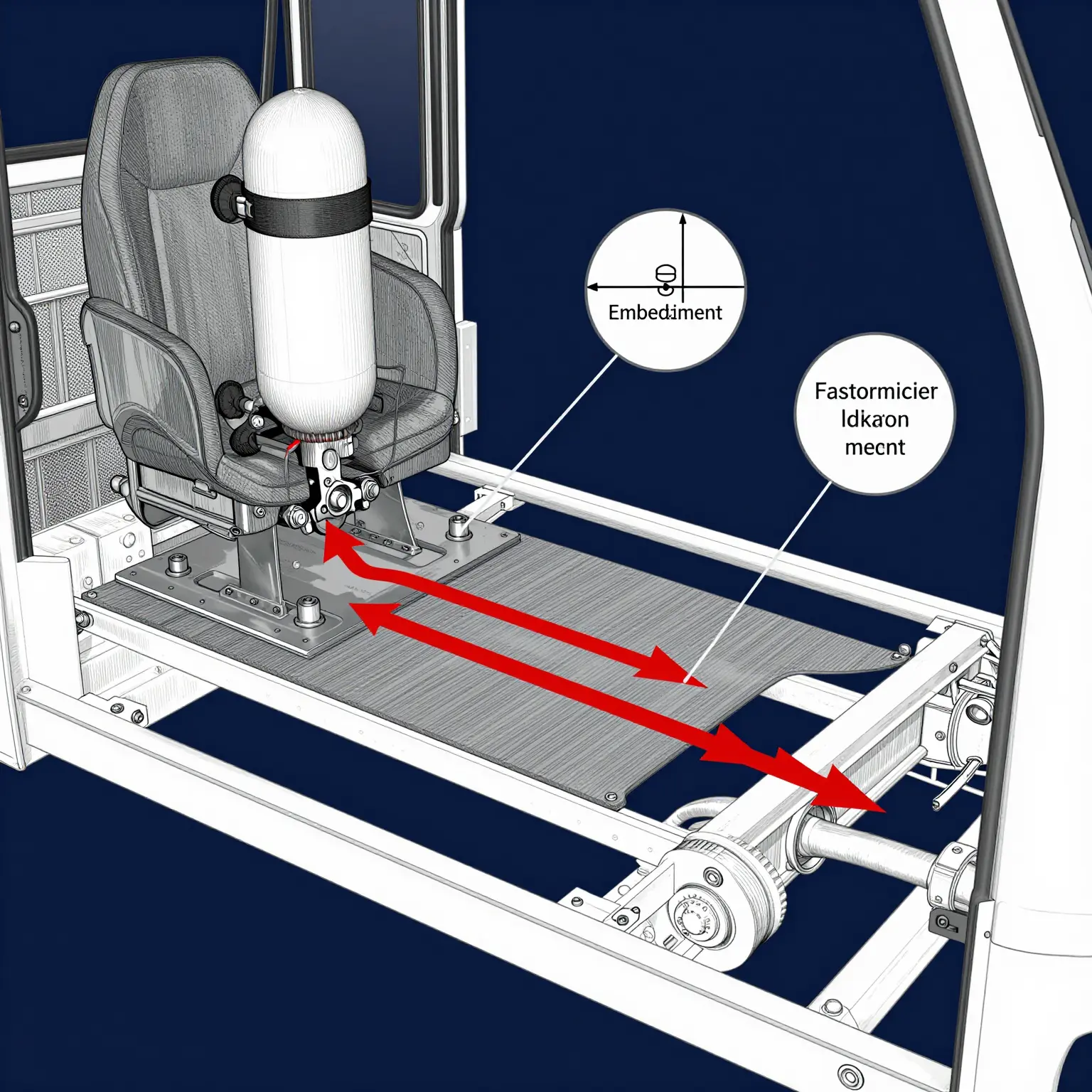
Figure: Restraint load path from the SCBA bracket through fasteners and reinforcement plate into the floor substrate and chassis-level structure, with embedment depth and edge distance called out.
In a deceleration, a filled SCBA cylinder stops behaving like stowed equipment and becomes a mass with momentum. The bracket has to arrest that mass, and every unit of force it arrests has to be handed to something stronger than the bracket. That handoff – bracket, fasteners, reinforcement plate, floor substrate, cab structure, frame – is the load path, and cab floor anchorage is the part of the chain the installer controls. If a link is weaker than the load it carries, or discontinuous, the chain fails there, however robust the bracket looks.
Restraint does not disappear because a bracket is heavy duty. It relocates to whichever component is least able to resist it.
Pull-out capacity is not a bracket specification. It is a property of the system. Floor substrate sets base material thickness and grade; the reinforcement plate spreads fastener load over a larger area and lowers local bearing stress; fastener grade governs how much tension and shear each bolt takes before it stretches or shears; embedment depth and edge distance decide whether the substrate tears out around the fastener before the fastener yields. Change any one of them, whether a thinner floor, a smaller plate, a lower-grade bolt or a hole set too close to a plate edge, and capacity falls non-linearly rather than proportionally.
| Variable | What it controls | Failure mode if under-designed |
|---|---|---|
| Floor substrate | Base material thickness and grade | Local yielding, panel distortion |
| Reinforcement plate | Load spread, bearing stress | Punching, plate bending |
| Fastener grade | Tension and shear resistance | Bolt stretch, shear-off |
| Embedment and edge distance | Substrate engagement | Tear-out, edge breakout |
Static proof testing and dynamic service are different questions. A pull test or a published static rating shows what an assembly survived once, under a slowly applied load. It says nothing about a filled cylinder oscillating on rough pavement for a decade, or about the amplified peaks produced when deceleration happens in milliseconds. Vibration, repeated shock, thermal cycling and fastener relaxation consume the margin a single static test appeared to prove. Dynamic capacity is the design basis; the static figure is a floor, not a ceiling.
The most common engineering error is assuming a seat frame is automatically an anchor. A seat frame is designed for seating loads (a seated mass, belt reaction forces, defined load factors), and its qualification covers that envelope only. Bolting a bracket to it adds a second mass with a different centre of gravity, a different load direction and eccentric moments the frame was never analysed for. Crew restraint compliance does not transfer by proximity. It transfers only by evidence.
Compliance rests on a verified, continuous load path from bracket to chassis-level structure: documented calculation or test data for the actual substrate and hardware combination, traceable fastener grades and installation torque, and confirmation that the path is not interrupted by trim, isolators, adhesive-bonded panels or a cab shell never intended to carry point loads.
A bracket is only as qualified as the continuous, verified path beneath it. Document the path, not just the part.
The chain is easier to follow in a diagram. It traces how the restrained occupant’s mass, multiplied many times over in a deceleration, leaves the bracket, travels down the seat pedestal, crosses the floor reinforcement plate and reaches the cab floor cross-member. Every arrow is a joint that has to stay sound. Interrupt one link and the strongest bracket in the industry becomes decorative hardware bolted to sheet metal.
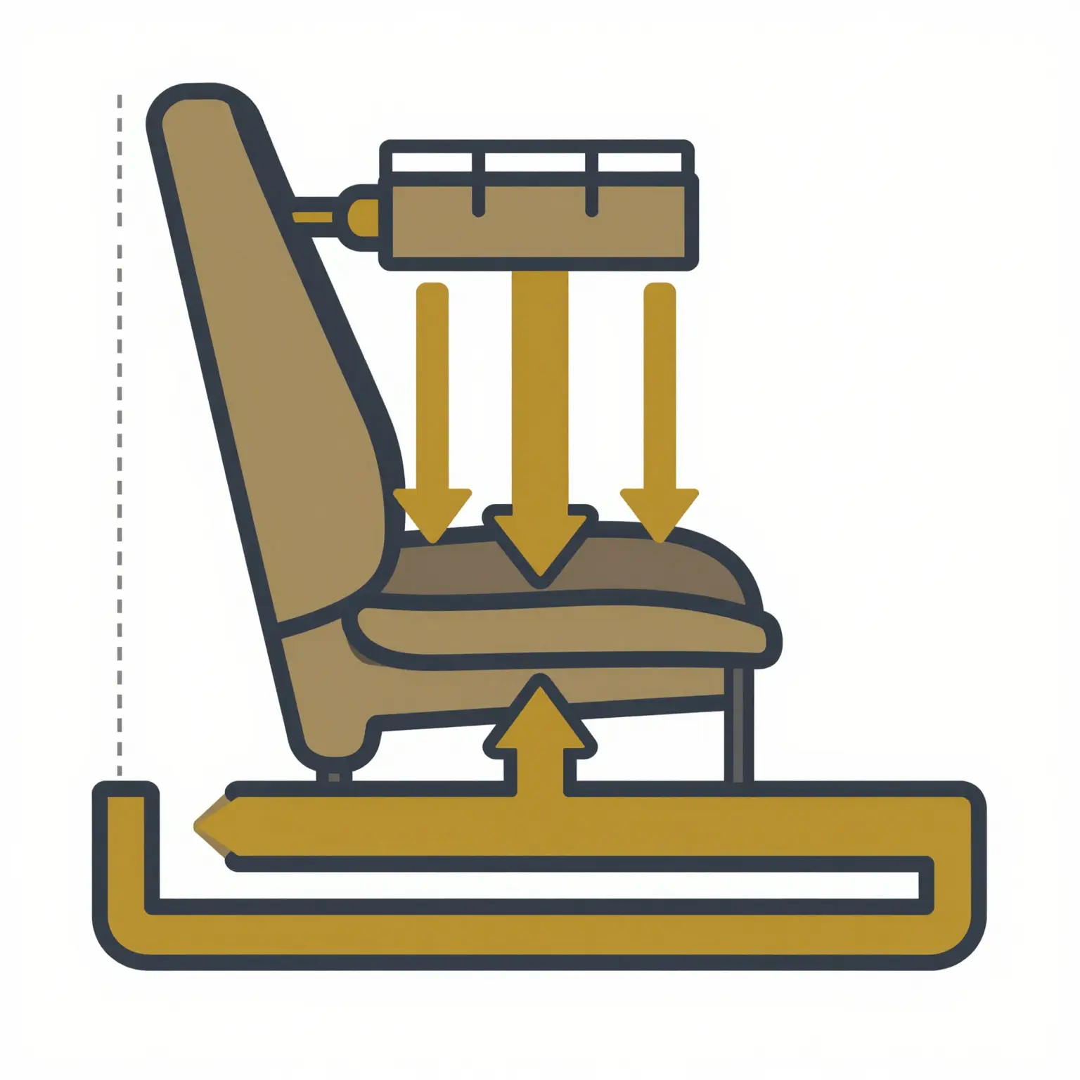
Figure: Schematic load path from SCBA seat bracket to cab floor cross-member. Arrows indicate force transfer direction; the horizontal spread at the base shows how load is distributed along the cross-member once it reaches structure.
That continuous path is what a compliance inspector looks for, not a seat tally on a specification sheet.
How to Verify Anchorage Before You Sign Off
A seat count tells you how many people the cab is supposed to hold. It tells you nothing about whether the bracket holding a filled cylinder will stay put in a frontal impact. Verifying cab floor anchorage is a physical, documentable process, and it runs in this order:
- Obtain the anchorage drawing and load calculations. Request the bracket anchorage drawing and the occupant and seat load calculations from the manufacturer or upfitter, and confirm the revision level matches the truck’s as-built serial number.
- Confirm substrate thickness and reinforcement at each bracket location. Measure the cab floor at every bracket footprint with an ultrasonic thickness gauge or caliper, and verify that doubler plates or under-floor reinforcement exist exactly where the drawing says they should.
- Check fastener grade and torque specification. Verify each bolt or nut is the specified grade and length with the correct washers, then torque it to the published value with a calibrated wrench and mark it as torqued.
- Verify that the bracket-to-floor interface is continuous with chassis-level structure. Trace the load path from the bracket through the floor and body structure into the frame rails, and document any gaps, stacked shims, sealant bridging or isolated sheet metal that interrupt it.
- Document each anchorage point against the as-built configuration. Photograph every anchor location, log its location ID, measured thickness, fastener grade and applied torque, and note any deviation from the drawing with the disposition that resolved it.
- Review retrofit and seat-replacement history. Pull the work orders and confirm whether seats, brackets or flooring were replaced or relocated, whether original hardware was reused, and whether holes were drilled outside the engineered pattern.
- Perform a final hands-on integrity check. Load and rock each seat assembly, look for movement, cracked welds, elongated holes or pulled fasteners, and correct anything you find before sign-off.
- Record the verified installation in the apparatus file. File the signed checklist, photographs, torque log and drawing revision with the vehicle’s permanent documentation, so the next inspector has something to compare against.
What survives inspection is that record: drawings, measurements, torque logs and photographs tied to a serial number. Seat counts are procurement shorthand. Crew restraint compliance is proven by a documented load path at every anchor point, and an auditor or investigator will ask for the file long before asking how many seats the cab has. Build it before you sign off, and keep it current through any future retrofit on municipal apparatus platforms.
Maintaining Anchorage Integrity Through the Vehicle’s Service Life
Crew restraint compliance is a condition to be sustained, not a certificate earned at delivery. Anchorage capacity degrades quietly: road salt and repeated wash-down thin the substrate, fasteners lose preload after repeated removal and reinstallation, and unapproved seat swaps introduce load paths the original design never accounted for. The same floor area also collects radios, tool brackets and storage, and a body repair can replace an anchorage plate with a different gauge of steel. Each of those narrows the margin between the strength the restraint system demonstrated and the loads it has to carry in a crash.
Anchorage points therefore deserve a defined inspection interval rather than attention after something looks wrong. Inspectors should check every cab floor anchorage for corrosion, cracking, elongated holes, missing or mismatched fasteners and deformation, and confirm that the installed hardware matches the engineering documentation. Every change, however minor, belongs in the vehicle file with the date, part numbers, torque values and the name of the person who did the work, so the configuration history survives ownership and service cycles. No seat pedestal, mounting plate or bracket should be modified without engineering review and written approval before work begins.
For procurement and maintenance teams, one rule covers it: any change to the SCBA seating configuration is a structural change. Relocating a seat, substituting a different bracket or adding floor-mounted equipment in the restraint zone requires re-verification of anchorage performance under the applicable NFPA framework, with documentation that survives audit. Treating those adjustments as routine maintenance is one of the most common ways a compliant apparatus drifts out of compliance without anyone noticing.
Frequently Asked Questions
These answers stick to what determines compliant crew capacity: verified cab floor anchorage, documented load paths, and evidence that traces back to the standards.
Does adding seats automatically increase compliant crew capacity?
No. Seat count is not the compliance metric. NFPA 1901 requires each riding position to have a properly anchored seat and restraint system, and adding seats without verified cab floor anchorage can reduce compliant capacity rather than increase it.
Can a seat-mounted bracket satisfy crew restraint compliance?
Generally, no. Restraint loads pass through the seat and its anchors into the cab structure, so a bracket bolted only to a seat frame has no verified load path behind it. That is the load path NFPA 1901 asks for and NFPA 1911 inspection looks for. Compliance depends on documented floor anchorage.
What documentation should a compliance officer request?
Request the anchorage engineering analysis, fastener and hardware specifications, installation instructions, pull-test results where they apply, and manufacturer statements of conformance to the NFPA 1901 seating and restraint provisions. Photographs of the completed floor anchorage help close the file.
Do aftermarket SCBA seat brackets void an existing installation?
Not automatically, but undocumented changes can. An existing installation stays defensible only if the added bracket preserves the original load path and hardware rating. If the retrofit changes anchorage geometry, treat it as a new installation and put it through fresh engineering review under NFPA 1901.
How many anchorage points are typically sufficient?
There is no universal number. Calculated restraint loads and the strength of the mounting surface set sufficiency, not a fastener count. Brackets commonly use four floor anchorage points, but the analysis establishes compliance, not the quantity.
Do anchorage requirements differ between new apparatus and retrofits?
The performance expectation is the same; the evidence trail differs. New apparatus should show anchorage design at build. Retrofits have to document how the existing structure carries the new loads, with NFPA 1911 inspection and maintenance records updated to reflect the change.
What to Specify and What to Stop Counting
A crew member in an SCBA seat is held by a chain that starts at the bracket and ends at the floor anchorage, and every link carries the restraint load together. If the bracket is sound but the floor anchorage lacks the backing plate, reinforcement or fastener specification to resist the certified load, the installation is non-compliant no matter how many seats appear on the build sheet. What has to be demonstrated is continuity: bracket to pedestal, pedestal to floor, floor pan to structural reinforcement, all traceable to the certified configuration.
Seat counts belong in inventory records, not in specification language. “Four SCBA seats” tells a procurement officer how many breathing apparatus positions the vehicle carries. It says nothing about whether those positions were validated against a restraint load case, and it invites substituting a bracket that fits the bolt pattern without matching the certified assembly. Replace the count with anchorage documentation: the bracket part number and revision, the floor reinforcement detail, fastener grade and torque values, and the test report or engineering sign-off that ties the installed geometry to the certification. Buyers comparing municipal fleet vehicle platforms can use this framing when scoping municipal vehicle enquiries; where chassis and body configuration requirements are assembled across multiple builds, cargo configuration requirements show how the same documentation discipline applies to floor structure and mounting.
The clauses below can be inserted directly into a specification as requirements.
- The bracket supplier shall provide the certified assembly part number, revision level, and the load case under which the assembly was qualified.
- The apparatus body manufacturer shall submit cab floor anchorage drawings showing reinforcement plates, fastener grade, and specified torque values for each SCBA seating position.
- Installation shall follow the bracket manufacturer’s published floor preparation procedure without deviation; any field modification shall require written engineering approval prior to installation.
- The contractor shall deliver as-built documentation confirming that each installed anchorage matches the certified configuration, signed by a qualified engineer.
- Seating capacity shall be certified per position against the anchorage documentation, not stated as an aggregate count.
- Post-delivery inspection shall include visual verification of anchorage hardware and torque confirmation on a documented sample of positions.
A compliant cab is one whose load path can be proven on paper and confirmed on the vehicle. Nothing else settles the question.