


Why PTO Torque Rating Governs Upfit Feasibility
Two numbers decide whether a tank truck upfit works: the hydraulic power the equipment demands, and the torque the power take-off can deliver continuously. If the pumps, blowers or vacuum systems draw more than the PTO can sustain, the build does not work, however well the rest of the truck is configured. PTO torque rating, quoted in lb-ft and fixed by the transmission’s power-take-off capability, is the specification that sets the ceiling.
Tank capacity answers a different question. Gallons determine how much product you carry, where the weight sits on the chassis, and whether axle ratings and wheelbase stay legal, but they say almost nothing about whether the truck can run the equipment. For vacuum and liquid-hauling work, those packaging constraints are laid out in our liquid waste truck lineup, and they remain secondary to the torque question.
The two get conflated on spec sheets and in sales conversations. A tank-and-truck package that looks generous on paper can stall on the first job, when continuous torque runs out. Settle the torque and the feasibility argument ends; capacity then becomes an optimization exercise.
How a PTO Torque Rating Is Established
A PTO torque rating is never a single number lifted off an engine data sheet. It comes out of a chain of multipliers plus one duty-cycle decision, and every link in that chain has its own ceiling. The figure means one thing: the torque a PTO output shaft can carry at a stated speed, under a stated duty cycle, and no more.

Engine Torque at the Governed PTO Speed
An engine torque curve plots how much twisting force the engine makes across its usable rpm band. What matters for an upfit is rated torque at the governed PTO speed, the rpm the PTO is actually held to, which is often not the rpm of peak torque. A stationary PTO runs at high idle or a programmed fast idle, so the governor pins shaft speed and with it the torque available to everything downstream. A chassis quoting 1,650 lb-ft of peak torque may hand a side-mount PTO noticeably less once the engine settles into its stationary working speed. That lower number is where the rest of the calculation starts.
The Transmission PTO Opening and Its Multiplier
The transmission PTO opening is the reinforced, gear-driven port cast into the side of the transmission case, where the PTO unit bolts on. The multiplier is the ratio between the transmission’s PTO drive gear, usually carried on the countershaft, and the mating input gear inside the PTO. When the drive gear is larger than the PTO gear, output torque rises as speed drops. The opening carries its own torque ceiling regardless of that arithmetic, so a favorable ratio cannot lift a mid-range gearbox into heavy-duty territory.
Ratio, Output Shaft, and Duty Cycle
The PTO unit’s own ratio compares its input gear with its output shaft, and multiplying incoming torque by that ratio sets rated output torque at a specific shaft speed. Duty rating then decides how much of that figure is usable. Intermittent duty permits the higher torque for defined short work cycles with a cool-down interval, the familiar pattern for spreaders and small winches. Continuous duty derates the same hardware, usually to roughly 60 to 70 percent, for service that runs for hours without a pause. Vacuum trucks built for liquid waste service and lube bodies sit firmly at the continuous end: a liquid-ring or rotary vane pump pulls for a full shift, oil temperature climbs and stays up, and no idle interval sheds the heat, so the conservative rating is the only honest one to design around.
Keep flywheel figures and PTO figures in separate lanes. Published PTO torque ratings describe the output shaft at a specified speed and duty cycle, not the flywheel, and mixing the two is the most common source of over-specification in tank and truck upfits. It shows up either as a pump the driveline cannot feed or as a tank the PTO cannot keep up with.

Figure 1. Schematic of the PTO torque path in a tank truck upfit, tracing rotational power from the engine through the transmission PTO opening, PTO gearbox and hydraulic pump to the tank-mounted equipment. The thinner return arrows show load feedback; the heavier stroke marks the duty-cycle branch.
Calculating the Torque Your Tank Equipment Actually Demands
The gallons stamped on a tank shell tell you how much product you can carry and nothing more. What decides upfit feasibility is the hydraulic pump torque demand the equipment creates at the PTO, because that is the load the transmission, PTO gearbox and driveshaft have to survive. Build the number one link at a time.
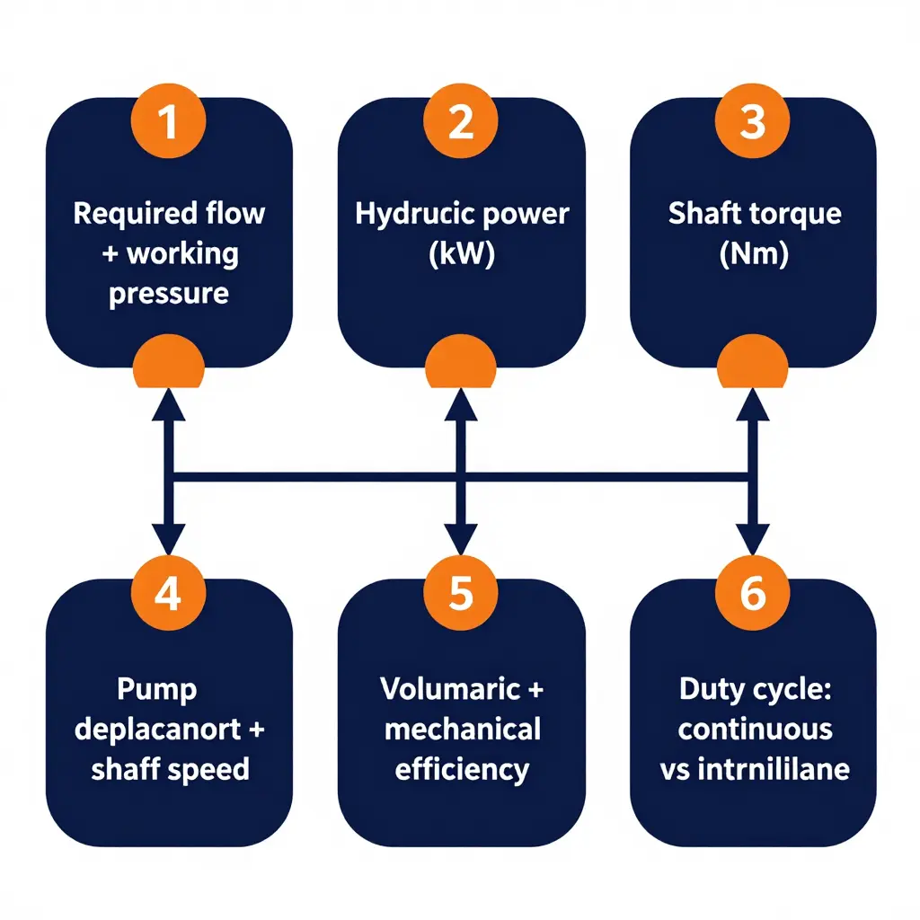
Step 1: Pin down flow and working pressure
Every implement in the system has two requirements that cannot be negotiated away: the flow it must move per minute, and the working pressure it needs to overcome static head, line losses, nozzle restrictions or vacuum lift. A spray bar and a high-pressure washdown wand can share the same pump but not the same pressure requirement, and that gap drives everything downstream.
Step 2: Turn flow and pressure into hydraulic power
Flow multiplied by pressure is power. In shop units, kilowatts are roughly pressure in bar times flow in litres per minute, divided by 600. That tells you how much work the fluid is doing. It says nothing yet about torque at the PTO shaft, which is where most spec sheets get misread.
Step 3: Convert power into shaft torque using displacement and speed
Torque is power divided by shaft speed, roughly kilowatts times 9,550 divided by rpm. Pump displacement enters the chain here. Displacement per revolution sets how much flow you get at a given PTO speed, so displacement and speed together define the operating point you are asking the engine to deliver. Two consequences follow. A large displacement turned slowly and a small displacement spun fast can produce the same flow, but delivering the same hydraulic power at half the shaft speed takes double the torque. Speed is your leverage on torque, and on many chassis the PTO ratio is the only lever you have.
Step 4: Add the efficiency penalty
Real hardware leaks and rubs. Volumetric losses mean the pump must sweep more flow than the implement consumes, and mechanical losses in the pump, bearings and PTO gearing mean the shaft supplies more torque than the ideal calculation suggests. Budget 15 to 25 percent on top of the theoretical figure, and ask the pump supplier for the curve rather than a single headline number. The worked examples below assume 85 percent overall efficiency.
| Duty | Flow (L/min) | Working pressure (bar) | Hydraulic power (kW) | PTO speed (rpm) | Ideal torque (Nm) | At 85% efficiency (Nm) |
|---|---|---|---|---|---|---|
| Fuel discharge pump | 380 | 8 | 5.1 | 1,000 | 48 | 57 |
| Lube oil transfer | 150 | 12 | 3.0 | 900 | 32 | 38 |
| High-pressure washdown | 60 | 150 | 15.0 | 1,200 | 119 | 140 |
Step 5: Match the result to a duty cycle rating
Finally, decide how long that torque has to be held. A discharge pump that runs two minutes per stop and a jetting system that runs an hour are different problems. PTO manufacturers publish continuous and intermittent ratings, and the PTO output torque you specify has to sit inside the right envelope. Short peaks, such as a cold-morning vacuum pull-down, can ride above the continuous figure within the intermittent thermal limit, but only for the stated duration.
The simple multiplier rule
Two rules of thumb carry most of the decision. Double the working pressure at the same flow and the required torque roughly doubles. Double the flow at the same pressure and hydraulic power doubles, which at a fixed shaft speed means roughly double the torque, because the pump must displace twice as much oil per revolution. Tank capacity appears in neither rule.
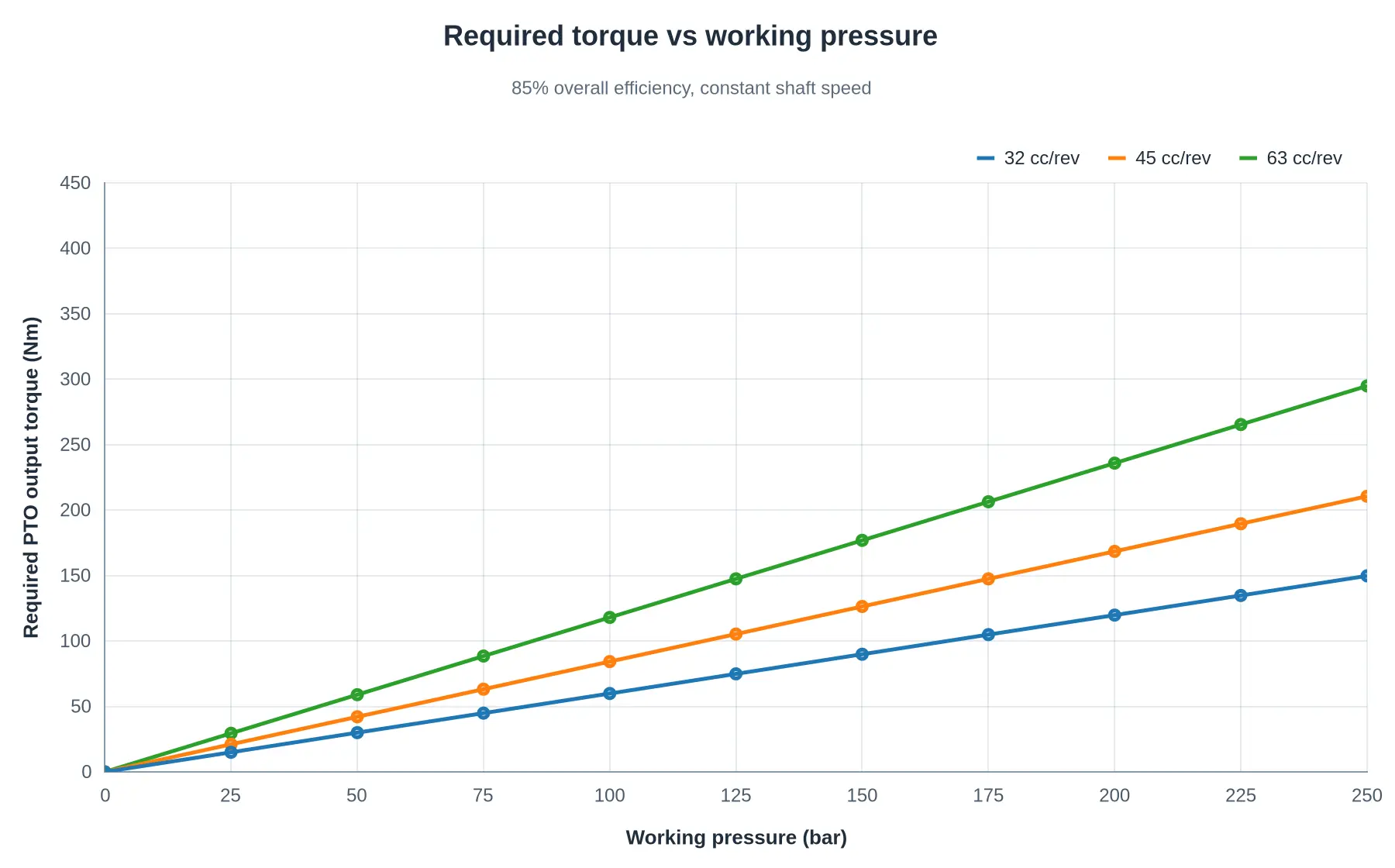
Where vacuum service breaks the pattern
Vacuum trucks and combination units follow the same chain from a different input. Liquid volume does not set the load; blower airflow and the vacuum level the job requires do. A blower rated at 400 mbar of vacuum draws very little torque at free air and a great deal more as the vacuum level rises and the lobes work against a restricted inlet, so the peak torque point sits at maximum vacuum with a nearly full tank, not during the first pull. Size the PTO against that worst-case corner and treat tank capacity as a payload question. Buyers comparing vacuum and liquid-waste upfits should confirm blower airflow and vacuum rating first, then work backward through the chain to a torque figure the chassis can carry all day.
Tank capacity scales with payload and chassis weight allowance. Required PTO torque scales with pump duty, meaning flow, pressure and duty cycle. The two columns in the table below therefore do not track each other.
Tank Capacity Versus Required PTO Torque by Upfit Type
| Upfit Application | Typical Tank Capacity (gal) | Pump or Blower Type | Typical Working Pressure | Required Continuous PTO Torque (lb-ft) | Minimum PTO/Chassis Class | Feasibility Note |
|---|---|---|---|---|---|---|
| Fuel delivery (bobtail) | 2,000 – 2,800 | Centrifugal product pump | 30 – 50 psi | 150 – 220 | Class 6, 250 lb-ft rated PTO | Payload-heavy but torque-light; metering and compartment plumbing are the real constraints |
| Lube service (multi-compartment) | 700 – 1,200 | Gear pump with reel circuits | 150 – 400 psi | 250 – 350 | Class 6, 400 lb-ft rated PTO | Small tank, heavy duty cycle; the chassis is chosen for PTO torque, not volume |
| Liquid waste vacuum | 3,000 – 5,000 | Rotary vane vacuum pump | 12 – 14 psi vacuum (24 – 28 inHg) | 300 – 420 | Class 7 – 8, 450 lb-ft rated PTO | Largest tanks in the table; torque tracks vacuum level and blower airflow, so axle and wheelbase ratings usually set tank size |
| Solid waste washdown | 1,500 – 2,500 | Triplex plunger pump with washdown gun | 1,000 – 2,000 psi | 300 – 450 | Class 7, 450 lb-ft rated PTO | High pressure adds heat rejection and side-load review on the PTO output shaft |
| Road cleaning (sweeper / jetter) | 1,000 – 2,000 | High-pressure reciprocating plunger pump | 1,500 – 2,500 psi | 350 – 500 | Class 7, 500 lb-ft rated PTO | Modest tank, highest continuous torque demand per gallon of any municipal upfit |
| Oil and gas service support | 2,000 – 4,000 | Triplex plunger pump or rotary blower | 1,000 – 3,000 psi | 400 – 550 | Class 7 – 8, 550 lb-ft rated PTO | Confirm continuous versus intermittent ratings; wellsite duty cycles often exceed catalogue assumptions |
| Dust suppression / construction water | 1,500 – 2,500 | Centrifugal or trash pump | 30 – 60 psi | 60 – 120 | Class 6, 200 lb-ft rated PTO | Lowest torque demand in the group; an easy fit even on lighter chassis with generous tanks |
Footnote: Torque values are representative continuous-duty output figures at PTO speeds of roughly 1,000 to 1,200 rpm. The same hydraulic power at a faster shaft speed means proportionally less torque. Ratings in the minimum-PTO column are the smallest that cover the top of the corresponding torque range, before any design margin. Actual requirements vary with pump displacement, relief setting, hydraulic circuit losses and PTO ratio, and must be confirmed against OEM data before an upfit is released. The pressure column mixes positive pressure and vacuum service, both expressed in psi; 12 to 14 psi of vacuum is about 24 to 28 inHg.
Buyers comparing high-capacity vacuum bodies against small-tank pressure equipment should review liquid waste chassis options to see how tank size and driveline ratings are paired in practice.
Why Tank Gallons Alone Mislead Buyers
Ask a buyer what size truck they need and the answer usually comes back in tank gallons. It is the number on the brochure, the one compared across three bids, the one that feels like it settles the question. It does not. Capacity follows from the chassis: it drives weight, payload and GVWR compliance, axle rating margins, center of gravity, and how much frame-rail space is left for pumps, hose trays and bodies. Get any of those wrong and the build either fails the scale ticket or rides badly, and a bigger barrel does not fix it.
Where buyers go off track is assuming those weight effects translate into a hard ceiling on what the truck can do. They do not. Tank capacity constrains upfit feasibility only indirectly, and a tank is the most forgiving component in the whole specification: shorten the barrel, drop a compartment or add baffling and the volume changes while the truck keeps working. Torque cannot be renegotiated the same way. A PTO rated at a given torque cannot create torque it does not have, not with a different tank, a bigger hose or a more aggressive operator. Capacity is the flexible variable; torque is the fixed one.
| Specification | Can it be renegotiated mid-build? | What it really governs |
|---|---|---|
| Tank gallons | Yes – shorten the barrel, resplit compartments, add baffling | Payload and GVWR headroom, axle rating margins, center of gravity |
| PTO torque rating | No – it is set by transmission, engine, and PTO gear | Whether the driven equipment can perform its job at all |
One exception deserves flagging before anyone signs a spec sheet. In vacuum service the load on the driveline comes from airflow and vacuum level, not from liquid volume, so a modest tank can still impose the highest torque demand in a fleet. That is how a compact unit built on purpose-built liquid-waste bodies can outwork a much larger truck, and why the same logic applies to solid-waste and debris bodies, where compaction and lift cycles rather than hopper size set the torque bill. Start with the torque the chassis and PTO can genuinely deliver, then size the tank to the payload it leaves behind.
Required continuous PTO torque vs. intermittent-duty rating
Nameplate PTO numbers are usually quoted at intermittent duty, but most tank and service bodies run their pumps or blowers for hours at a time. The chart ranks five common upfit applications by the continuous torque they actually demand, with the intermittent-duty rating normally used to spec the PTO plotted alongside.
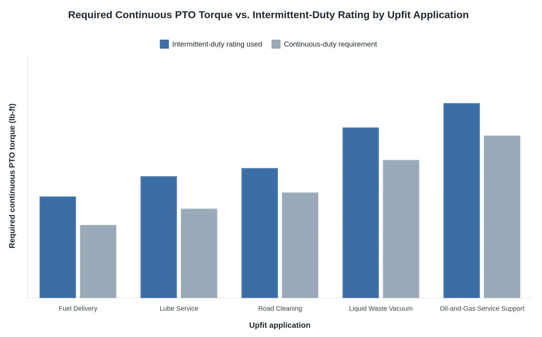
Figure: Required continuous PTO torque (lb-ft) by upfit application, ranked from lowest to highest continuous demand, with the intermittent-duty rating commonly used for PTO selection shown alongside.
Bottom line: Fuel delivery starts the ranking near 180 lb-ft of continuous demand. Oil-and-gas service support and liquid waste vacuum sit at the top, where continuous demand passes 400 lb-ft and a light-duty PTO and its driveshaft run out of margin.
Caption: The shaded shortfall between the two bar sets is exactly what produces under-torqued upfits, a PTO sized to its nameplate intermittent rating rather than to the duty cycle it will see in the field. Values shown are representative planning figures for comparison only and must be verified against OEM PTO data and the specific pump or blower curve before any upfit is approved.
Specifications to Verify Before Approving a Tank Upfit
Before you approve a tank package, run every candidate chassis through the same checklist, whether the body is a liquid waste truck configuration or a fuel and lube delivery unit, and read it in the same order you read the torque curve, starting at the PTO pad. Each line is a yes-or-no check, not a suggestion:
- Confirm PTO output torque at the intended PTO speed, not at peak engine rpm.
- Verify the PTO duty-cycle rating matches your application’s load and run-time profile.
- Match pump displacement and maximum working pressure to nozzle and hose demand.
- Check the hydraulic circuit relief setting against the pump’s rated maximum pressure.
- Confirm the transmission offers a PTO provision with a usable drive gear ratio.
- Recalculate chassis GVWR and rear-axle rating after adding tank, payload, and fluid.
- Verify PTO cooling capacity and oil volume for continuous duty in summer heat.
- Cross-check every item above against OEM upfit guidelines before final approval.
If any single line fails, fix it before the tank is ordered. The PTO torque rating sets the ceiling, and every remaining item on the checklist has to live underneath it.
What Happens When Available Torque Falls Short
An under-torqued upfit rarely announces itself on the spec sheet. It shows up six months later, in the shop, one component at a time. The failure modes are predictable because every one traces back to a single deficit: the PTO cannot deliver the torque the hydraulic pump demands at peak pressure.
- Pump stall and creeping cycle times at peak pressure – the engine-side torque ceiling is reached before the pump’s pressure-compensation point, so the pump lugs down instead of holding flow.
- Relief-valve bypass and heat generation – flow that cannot be converted into useful work dumps across the relief valve, turning hydraulic horsepower straight into heat.
- Accelerated PTO gear wear – continuous torque overload at the gear mesh raises contact stress and breaks down the oil film beyond the gear set’s design envelope.
- Repeated PTO clutch or shear-section failure – the clutch or shear coupling becomes the system’s de facto torque fuse and trips every time the pump loads up.
- Hydraulic overheating that shortens component life – sustained bypass flow thins the oil, and degraded viscosity accelerates seal, hose and pump wear.
- A reduced practical duty cycle – cool-down and repair intervals between work cycles quietly cut daily throughput, even though the truck’s nominal capacity looks fine on paper.
Why the Symptoms Surface Late
Under-torqued operation is a margin problem, not a defect, so it passes inspection and survives the first few weeks of light work. It also interacts badly with tank size: a larger tank moves more mass and often demands more flow, which pushes an already thin torque margin further into overload. Fleets running road-cleaning truck bodies with high-flow sweep and spray circuits feel this first, because those systems hold peak pressure for long stretches rather than in short bursts.
That is the core lesson for anyone comparing tank gallons against PTO ratings across municipal truck upfits: verify torque margin before the body is mounted, because the failures appear after commissioning, not at spec review, when there is still time to change the PTO ratio, pump displacement or body spec.
Share of Available PTO Torque Consumed by Subsystem
A tank truck’s PTO gives you a fixed torque budget, and every driven function draws from that same pool. The doughnut chart shows how continuous torque demand typically breaks down on a representative multi-function tank configuration, where the vacuum blower dominates the load and the remaining functions split what is left.
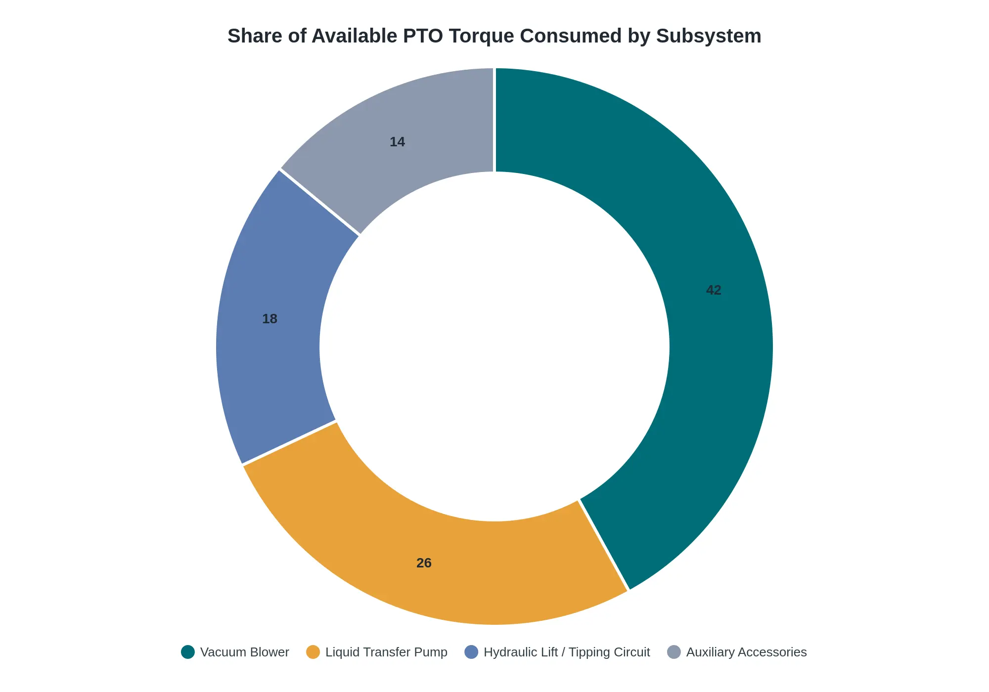
| Subsystem | Share of Available PTO Torque |
|---|---|
| Vacuum Blower | 42% |
| Liquid Transfer Pump | 26% |
| Hydraulic Lift / Tipping Circuit | 18% |
| Auxiliary Accessories | 14% |
| Total | 100% |
Any subsystem added after the initial torque budget is set draws from the same fixed pool, so no function gets a private reserve of PTO capacity. That is why simultaneous operation has to be evaluated as a combined load rather than one function at a time.
When you spec a liquid waste and vacuum body, the 42% blower slice is the load that most often pushes a marginal PTO rating over the edge, so confirm continuous-duty torque at your intended engine rpm before you commit to tank gallons.
Matching Tank Size to Available PTO Torque
Once you accept the PTO torque rating as the fixed constraint, tank size stops being a design input and becomes a consequence. That reads backward at first, since buyers shop in gallons rather than pound-feet, but the pump, not the vessel, is what the transmission has to carry. What follows are the levers an upfitter can genuinely pull, roughly in order of cost and disruption.
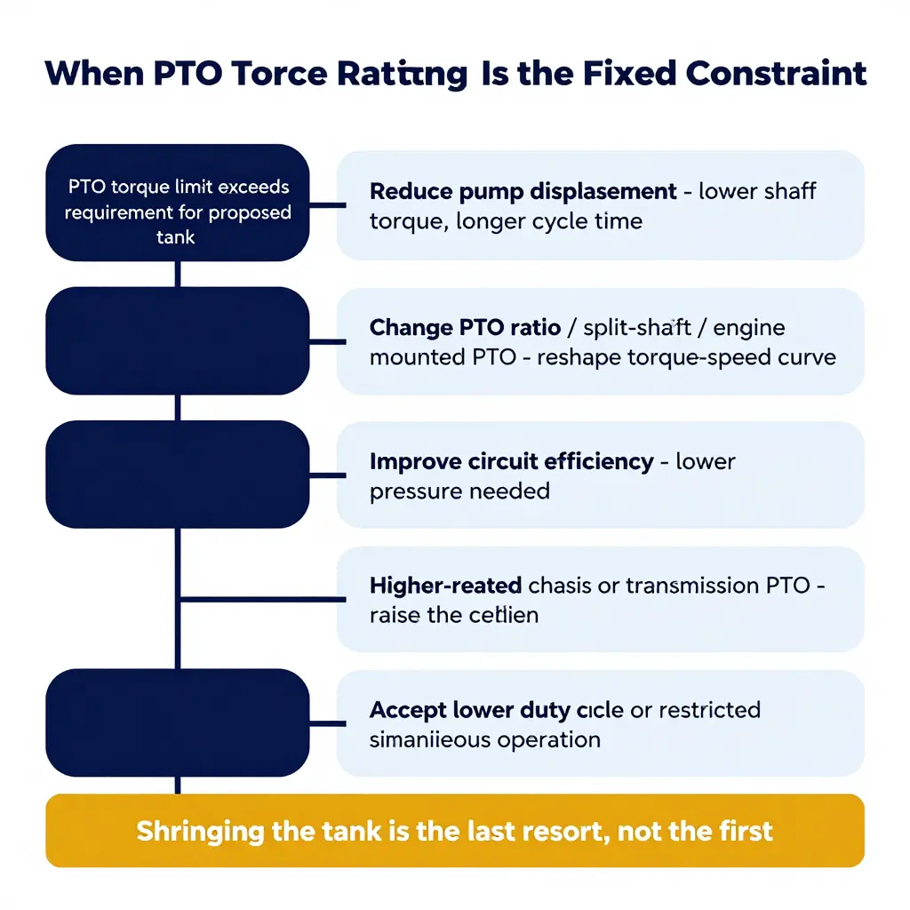
1. Reduce pump displacement
A smaller displacement per revolution lowers shaft torque at any given discharge pressure, which lets the circuit live inside the PTO envelope without changing the chassis.
Consequence: cycle time stretches. A job that ran in 20 minutes may take 28 minutes. The tank still fits the truck, but the truck earns less per shift.
2. Change the PTO ratio, or move off the transmission
Reshaping the torque-speed relationship with a different PTO gear ratio, a split-shaft PTO, or an engine-mounted (crankshaft or front-engine) drive changes how much torque the drivetrain sees for a given flow.
Consequence: you gain headroom or pump speed without shrinking the pump, and pay in hardware cost, added weight, packaging space and, with a split-shaft unit, sometimes a restricted road speed while engaged.
3. Improve circuit efficiency to reduce required pressure
Larger suction lines, shorter runs, fewer elbows, a properly sized cooler and clean filtration all cut pressure drop, and shaft torque tracks pressure almost linearly.
Consequence: the same flow arrives with less heat and less torque demand, which buys tank capacity back for the price of better plumbing.
4. Step up to a higher-rated chassis or transmission PTO provision
Some chassis publish a more generous torque allowance at the PTO aperture, and specifying one raises the ceiling outright.
Consequence: this is the cleanest engineering answer and usually the slowest and most expensive, because it reopens chassis selection, lead time and purchase price.
5. Accept a lower duty cycle or restricted simultaneous operation
Running vacuum and discharge functions one at a time, adding cool-down intervals or capping continuous run time keeps the hardware comfortably inside its rating.
Consequence: no new parts and no new truck, but the operational envelope narrows and dispatch has to plan around it every day.
Why the tank is the last thing to shrink
Reducing tank capacity is the last resort, not the first. Gallons are the cheapest variable in the equation: payload can be trimmed through partial fills, denser or lighter media, and close attention to axle and bridge limits, without touching the drivetrain, the PTO or the hydraulic circuit. Cutting the tank costs revenue on every trip for the life of the truck.
It shows up in specific buying decisions:
- Comparing vacuum and liquid waste upfits, read the torque allowance before the capacity badge.
- On chassis headed for dump bodies, hoist pump duty cycle rather than body volume tends to drive the PTO decision.
- With trailer-mounted tank equipment, the tractor’s PTO provision becomes the binding constraint the moment you leave the drawbar.
Frequently Asked Questions
Does a larger tank always require a higher PTO torque rating?
No. The driven equipment sets the requirement, not the tank. A 3,500-gallon body running a low-flow transfer pump can demand less torque than a 1,200-gallon body driving a high-volume blower, because torque comes from pump displacement and working pressure, not from the gallons sitting behind it. Size the PTO to the pump or blower curve first, then confirm the chassis can legally carry the tank.
What is the difference between continuous and intermittent PTO torque ratings?
A continuous rating is the torque a PTO can carry indefinitely without exceeding its thermal limits. An intermittent rating covers short-duty peaks the unit tolerates only for limited periods. One unit might be published as 300 lb-ft continuous and 400 lb-ft intermittent, so a quoted rating means little unless you know which duty class it belongs to. Compare like with like when matching a PTO to a pump or blower.
How do I estimate the torque my pump or blower needs?
For a hydraulic pump, multiply pressure in psi by displacement in cubic inches per revolution and divide by 75.4 to get torque in lb-ft. Then add 15 to 25 percent for efficiency losses, cold oil, breakaway loads and relief settings. For blowers and positive-displacement pumps, take the manufacturer’s published brake-horsepower curve and convert to torque at the driven-shaft speed: horsepower times 5,252 divided by rpm. If you are specifying vacuum or liquid-waste equipment, the liquid-waste truck body options show how pump packages map to real chassis ratings.
Can PTO torque capacity be upgraded after the upfit is complete?
Sometimes, but it is rarely economical. Raising capacity after the fact usually means swapping the PTO, adding an oil cooler, or resizing the driveline and pump mount, and those costs often erase the savings of the original build. Getting the rating right during design is cheaper and cleaner than a retrofit.
Is tank weight or PTO torque the real limiting factor for upfit feasibility?
PTO torque rating is usually the harder ceiling, because it is fixed by the transmission model, the PTO aperture and gear-tooth limits, while tank capacity is constrained by GVWR and axle ratings that can sometimes be re-rated. Upfit feasibility still fails on whichever constraint runs out first, so verify both the torque envelope and the loaded weight before committing to a spec. A build that satisfies one limit but not the other is not a viable truck.
A Torque-First Sequence for Upfit Decisions
Gallons are a packaging variable. PTO torque rating is a drivetrain constraint. The constraint has to be satisfied before the variable is optimized.
In tank and truck sales conversations, that principle is easiest to apply as a fixed order of work rather than a checklist read in whatever sequence the spec sheet happens to print.
- Establish the required equipment flow and pressure. Begin with the duty the driven equipment must perform: the flow rate and pressure the pump, blower, vacuum or hydraulic circuit genuinely requires at operating conditions, not the peak figure on a marketing sheet.
- Convert that duty into continuous shaft torque. Translate flow and pressure into the torque the pump shaft must absorb continuously, which is the number the drivetrain lives with hour after hour. Hydraulically driven bodies, such as the boom and winch circuits on tow truck configurations, follow the same logic, since their pump draws from the same transmission-driven circuit.
- Confirm the chassis PTO provision and duty rating against that figure. Verify that the transmission offers a compatible PTO port, that the PTO unit’s torque capacity exceeds the continuous requirement with margin, and that its duty classification (intermittent or continuous) matches how the equipment will be run.
- Size the tank against the remaining payload and packaging allowance. Only once the drivetrain is settled does tank volume follow, because the tank is what is left after the PTO hardware, body structure and payload budget are accounted for.
Following this order prevents the common outcome of a correctly sized tank mounted on an incorrectly specified drivetrain. Judging upfit feasibility from tank gallons inverts the sequence and hides the mismatch until the truck is working. Verification against the OEM upfit guidelines remains the final gate, where published figures, application notes and derating conditions are confirmed for the exact chassis and body combination before the build is released.