

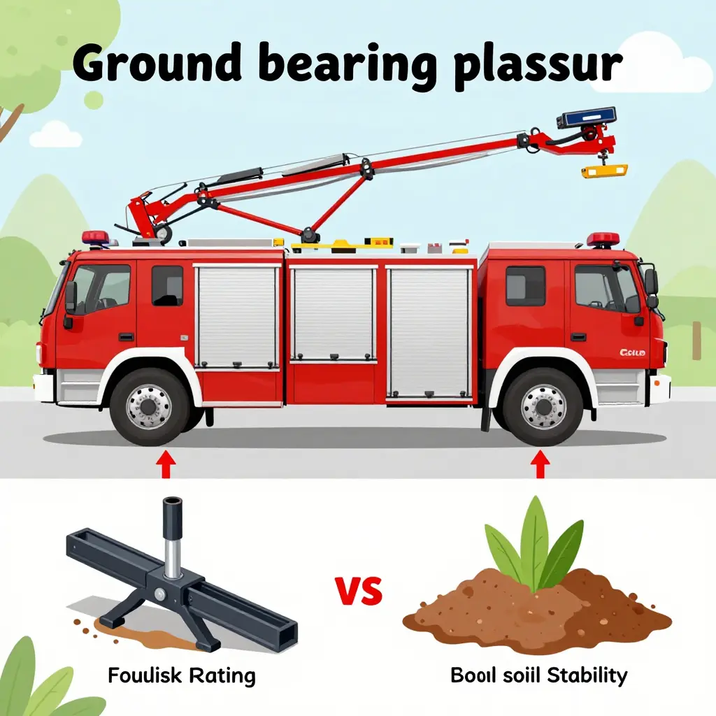
Why Ground Bearing Pressure, Not Jack Rating, Governs Fire Truck Outrigger Setup
An outrigger jack rated to 100,000 pounds can still drop through the ground under it. The number on the cylinder describes what its rod, barrel, leg, and beam can carry in a test rig; it is a limit of the hardware, not a promise about the site. Whether the apparatus stays level depends on the ground. Every setup comes down to ground bearing pressure: the outrigger load divided by the area of the float that passes it into the surface. Push that pressure past what the soil, asphalt, or engineered pavement can resist and the float sinks, the chassis shifts, and the rig goes over, whatever the jack is rated to hold.
Aerial ladders and platforms ask the most of outriggers because their long booms work far off center. The people who answer for that stability in the field and in the shop — fleet managers, apparatus engineers and technicians, safety officers, and the crews who set the pads — are the audience for what follows. The limit of any setup is set by contact area, float size, soil type, and how the load is shared between outriggers, and the same mechanics govern any outrigger-stabilized lifting equipment built on the same principles.
Jack Rating: Concept, Limits, and Why It Is Not a Stability Guarantee
A jack rating is the capacity assigned to one outrigger cylinder: the most load its mount and structure are designed to hold in a defined test condition. It is quoted in kilograms or tonnes and reflects the strength of the rod, barrel, pin, and welds. Like any component rating, it belongs to the part, not to the vehicle.
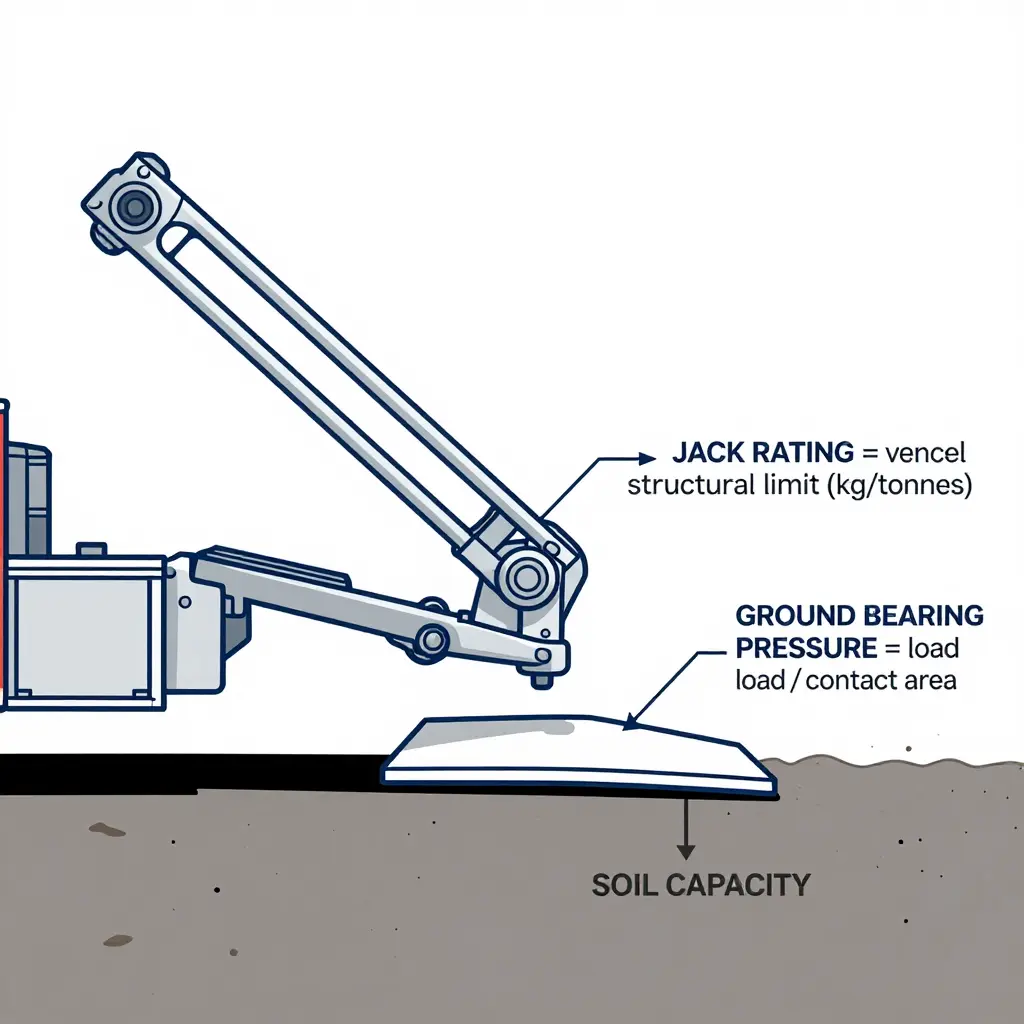
Ratings are built from a capacity figure and a safety factor. A cylinder rated at a given tonnage usually carries a structural margin somewhere between 1.5x and 2x, sometimes more, so that the shock of deployment does not push the steel to yield. That margin protects the cylinder; it tells you nothing about the soil under the pad.
Component Limit Versus Transmitted Load
Here is the distinction that gets missed: a jack rating bounds the load a cylinder can transmit, but not the pressure that load puts on the ground. Ground bearing pressure is load divided by contact area.
Put it in variables. Let L be the transmitted load in kilograms and A the pad’s contact area in square meters, with L held inside the jack rating. Pressure is L / A, and every change in that answer comes from the pad. Halve the pad area and the pressure on the soil doubles, even though the cylinder is doing exactly what its rating allows.
| Parameter | What it bounds | Typical unit | What it does NOT guarantee |
|---|---|---|---|
| Jack rating | Structural and hydraulic capacity of one cylinder | kg / tonnes | Whole-rig stability |
| Safety factor | Margin above rated capacity | ratio (e.g., 1.5x-2x) | Soil bearing strength |
| Transmitted load | Force passed to the pad | kg / tonnes | Ground pressure |
| Contact area | Pad footprint | m² | Cylinder strength |
Why Outrigger Setup Treats It as an Input
A sound outrigger setup treats the jack rating as one input among several. The cylinder can be perfectly good while the ground under it fails. That is why engineers check soil capacity, pad size, and how the load divides across all four outriggers before they trust the number stamped on a jack. Departments buying municipal apparatus platforms make the same calculation when they choose and specify stabilization hardware.
What Is Ground Bearing Pressure (GBP)?
Ground bearing pressure (GBP) is the force transmitted through a jack, outrigger, or stabilizer divided by the effective contact area of its float or pad – not by the jack’s rated capacity.
An outrigger passes the weight of the apparatus, plus the live loads of an aerial device or elevated stream, into the ground through a small steel or timber footprint. Whether the rig stays level or punches through depends on how much pressure that footprint puts on the soil. The relationship is simple:
GBP = Load / Area
Load is measured in pounds (lb) or kilograms (kg); contact area in square inches (in²) or square meters (m²). The result is expressed in psi, kPa, or tonnes per m².
GBP Versus Jack Rating
A jack rating is a mechanical limit inside the machine: the most force the hydraulic cylinder is built to exert or hold. Ground bearing pressure is what happens when that force meets a particular pad on a particular soil. The two numbers do not track each other. A jack running at a fraction of its rated load can still overload the ground beneath it.
How Small Footprints Concentrate Load
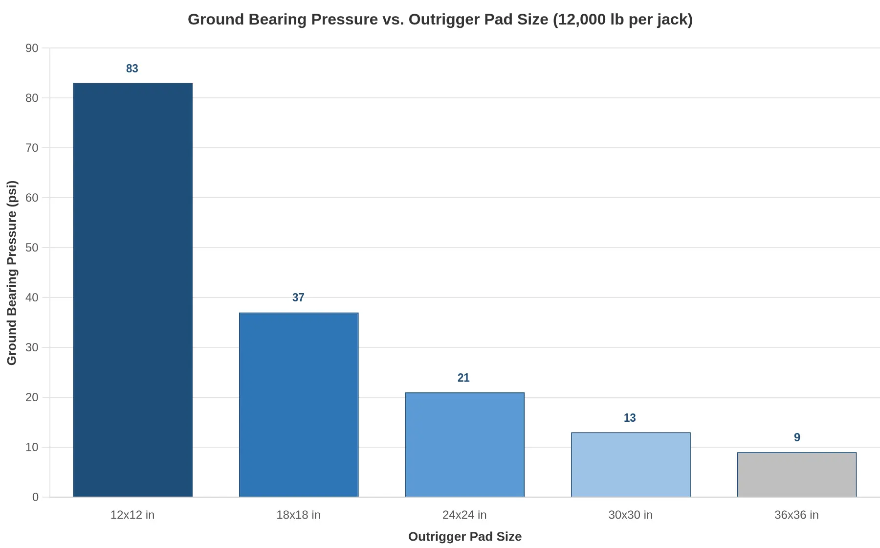
Contact area sits in the denominator, so a smaller pad multiplies the pressure. Spread a 20-ton (40,000 lb) outrigger load over a 12 x 12 in (144 in²) pad and you get about 278 psi. Cut the pad to 72 in² and the same load produces roughly 556 psi, with nothing changed at the jack. Once that pressure passes the soil’s allowable bearing capacity, the pad settles, the outrigger loses contact, and the rig starts to tilt. Stability is gone at that point.
Soil Capacity and the Soil-Jack Interface
Everything rests on the interface between pad and soil. Stiff ground takes high pressure; saturated or weak ground does not. The table gives representative presumptive allowable bearing capacities, but site conditions always need verification.
| Soil / Material | Allowable Bearing Capacity (psf) | Approx. (psi) |
|---|---|---|
| Crystalline bedrock | 12,000 | ~83 |
| Sedimentary rock | 4,000 | ~28 |
| Compacted gravel / crushed stone | 3,000 | ~21 |
| Compacted sand / silty sand | 2,000 | ~14 |
| Compacted clay / sandy clay | 1,500 | ~10 |
| Soft clay, silt, organic soil | 500-1,000 | ~3.5-7 |
The lesson holds for municipal apparatus and aerial ladders alike: size pads and cribbing to the soil, not to the jack. Bigger floats, timber cribbing, and ground you have actually checked are what keep bearing pressure in a safe range.
Factors That Determine Ground Bearing Pressure During Outrigger Setup
Ground bearing pressure moves with the site, the pad geometry, and the load on the boom, while a jack’s rating never moves. A fire truck outrigger setup holds or does not hold on the factors below, which are the same ones that govern any outrigger-equipped lifting equipment.
Float or pad footprint. Larger floats spread the jack reaction over more area and lower the pressure in proportion. An undersized pad concentrates it, and during deployment that can push past what the soil will carry.
Soil type and moisture. Loose sand, saturated clay, and undocumented fill carry far less than compacted gravel. Wet weather weakens the ground without changing the jack rating by a pound, and the risk of excessive bearing pressure rises with it.
Slope and surface deformation. On uneven or sloping ground the float tilts, contact area drops, and the reaction moves toward the outrigger edge, where local pressure spikes.
Load distribution among outriggers. As the aerial slews, weight shifts between jacks. The most heavily loaded outrigger carries the highest bearing pressure, so the worst-case corner is the one to check before extending.
Dynamic and wind-induced loading. Gusts, stream reaction forces, and sudden boom movement add transient loads and impact factors that can exceed the static calculation for a moment.
Cratering and undermining. Sustained load or water can punch a float into soft ground, shrinking the bearing area. Nearby excavations make it worse, and the pressure keeps climbing as the hole deepens.
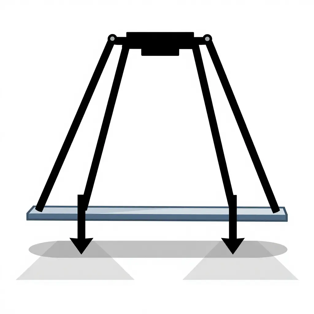
The Physics of Overturning Moment and Load Transfer
Extending an aerial and putting it to work builds a set of forces the chassis and outriggers have to balance. Following that load path is where any safe outrigger setup starts.
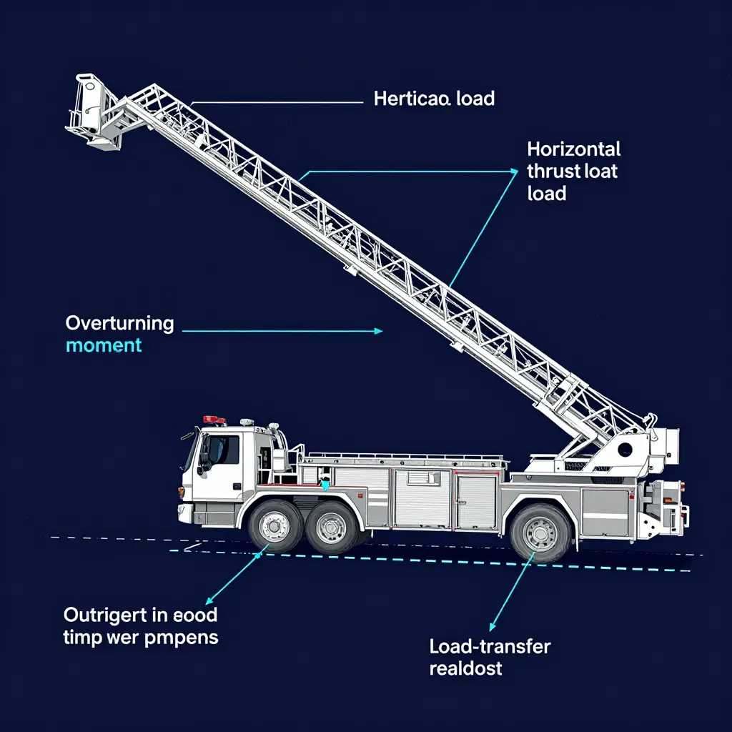
Where the Overturning Moment Originates
Two loads matter on the aerial. The vertical load — boom or ladder weight, nozzle, water, personnel, and equipment — acts through a center of gravity that moves outward as the device extends. The horizontal thrust — nozzle reaction, wind, and dynamic movement — acts above the turntable and adds a second couple.
Multiply the vertical load by its horizontal distance from the fulcrum and you have the dominant overturning moment. The fulcrum is the tipping line, the line through the outrigger pads on the loaded side. More reach or more load increases the moment, and the tipping line becomes the axis the whole rig would rotate about.
How Outrigger Reactions Resist the Moment
The rig stays up as long as the moment from the outrigger pad reactions is larger than the overturning moment. On level, stiff ground the pads share the reaction, and each one carries a modest share of the total. The balance itself is simple; what makes it delicate is the geometry and stiffness of the four support points.
Why Soft or Uneven Ground Shifts the Load
On compressible or uneven ground the firmest contact point takes far more than its share. The chassis rotates a little, the load migrates toward one outrigger, and at that pad the bearing pressure — reaction divided by contact area — climbs fast. A small change in support condition is enough to multiply the pressure at the critical pad.
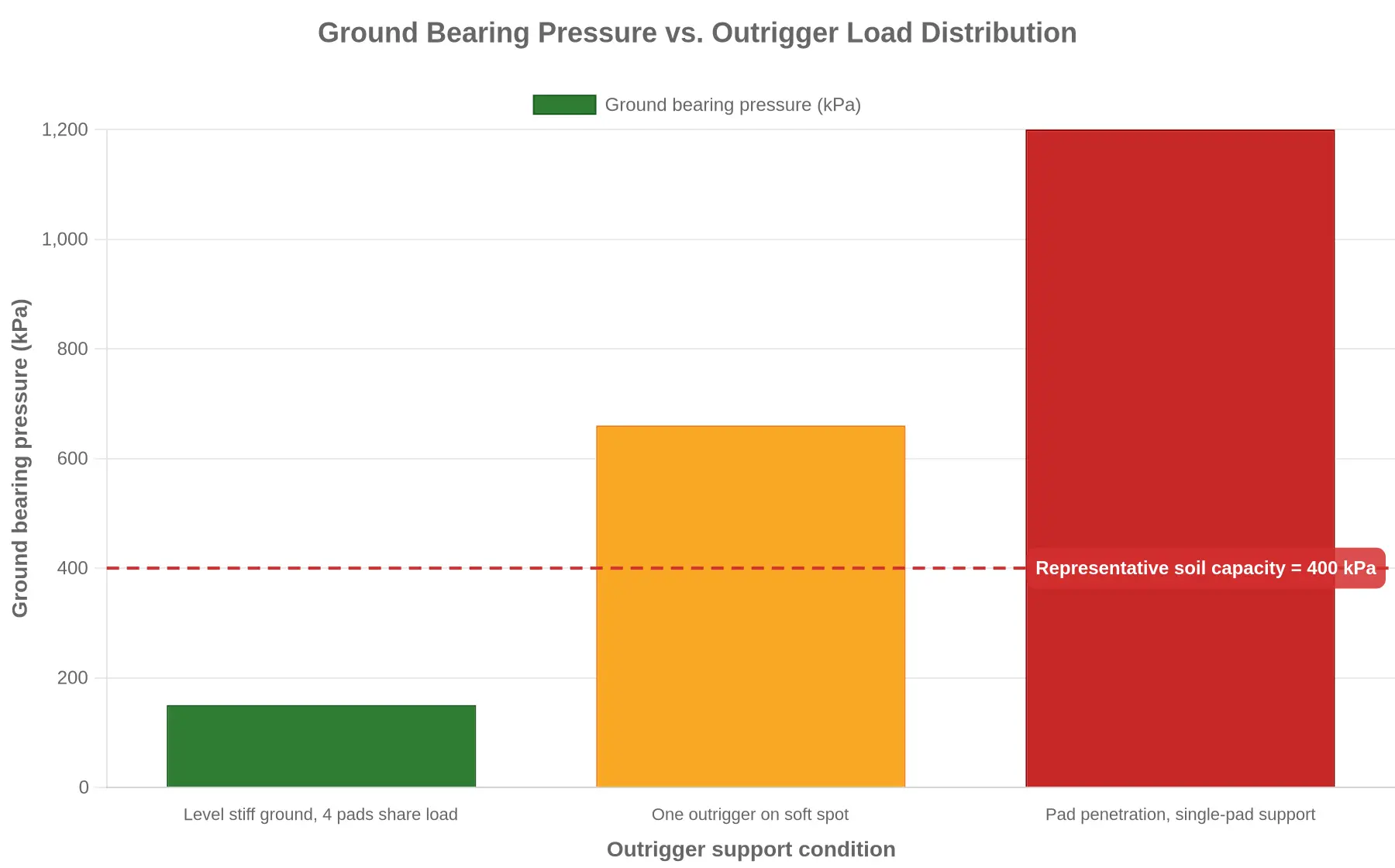
| Support Condition | Share of Total Reaction | Pad Reaction (kN) | Ground Bearing Pressure (kPa) |
|---|---|---|---|
| Level, stiff ground (4 pads) | 25% per pad | 60 | 150 |
| Soft spot under one outrigger | ~55% on one pad | 132 | 660 |
| Pad penetration, single-pad support | 100% on one pad | 240 | 1,200 |
Why the Ground, Not the Jack, Decides
Once the required pressure passes the soil’s capacity, the sequence runs downhill. The pad penetrates, the outrigger drops, and the rig rotates about the tipping line, which lengthens the moment arm and increases the overturning moment. The load redistributes suddenly, driving still more force into the failing point, and each increment feeds the next. That is how a rig tips.
This is why a jack rating is irrelevant if the ground fails. A jack rated far above the calculated reaction will hold perfectly while the soil under it shears and settles. All the jack does is transmit force; the ground has to be able to take it. Pad sizing, load-spreading cribbing, and a surface you have verified are what keep the rig upright, and a bigger jack is not. Fleet managers evaluating municipal apparatus platforms should treat soil verification and pad area as the stability variables that govern every aerial deployment.
Key Takeaways
- The overturning moment equals the aerial load multiplied by its horizontal distance from the tipping line.
- Outrigger pad reactions create the resisting moment that counteracts it.
- Uneven or soft ground concentrates load onto a single outrigger and multiplies ground bearing pressure.
- Exceeding soil capacity causes penetration, sudden load redistribution, and potential tip-over.
- A higher jack rating cannot compensate for a ground failure – capacity must be assessed at the soil, not the jack.
Why Ground Bearing Pressure, Not Jack Rating, Decides the Setup
A rig can be fully compliant and still sink if the ground cannot carry the load. On municipal emergency vehicles, that is the difference between a working platform and a tipping hazard.
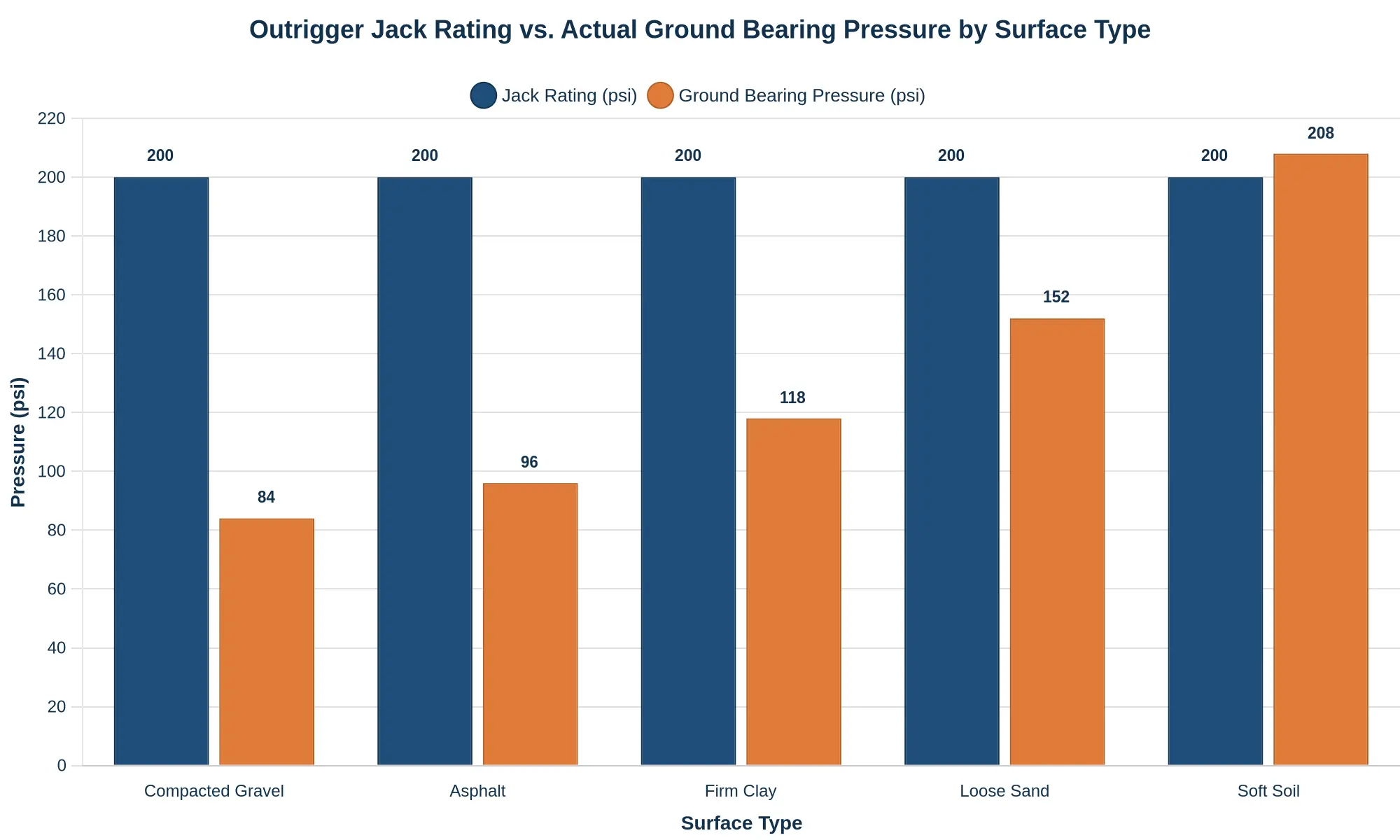
The jack rating is fixed hardware; it reads the same on gravel and on soft soil, so it cannot explain why one position is rock-solid and the next is not. Only the pressure actually reaching the surface can. When that pressure on weak ground climbs toward or past what the soil can safely carry, the remedy is a larger float or cribbing to spread the load over more area. That is why ground bearing pressure, not jack rating, governs whether a setup is viable.
Ordered Setup Checklist for Outrigger Deployment
Two things drive this sequence: ground bearing pressure (GBP) and rig stability. The jack rating says what the hardware can lift; the soil says what the rig can stand on. Work through the steps in order, and do not move to the next one until the current one is verified. Departments that also run heavy lifting gear will recognize the same stabilization logic behind crane-lifting solutions.
Assess the ground before the wheels stop rolling. Identify soil type, moisture, fill, voids, and buried utilities. What matters is the pressure the surface can accept, not the jack’s rated capacity; weak soil lowers that ceiling and erodes stability with it.
Measure slope and surface irregularities. Record pad-side grades and stay off crowned or soft edges. A tilted footprint shifts the reaction and can start a tip well before any jack reaches its rating.
Position the apparatus to balance the load. Spot the rig so the outrigger spread divides the reaction evenly and the center of gravity stays inside the stability envelope. Skewed positioning loads one foot and shortens the effective base width.
Size and place the load-spreading floats. Divide the outrigger reaction by the soil’s allowable bearing pressure to get the pad area you need. On low-capacity or unverified ground, use larger floats or timber cribbing to widen the contact area and bring GBP down.
Seat each pad flat and centered. A level, fully seated pad transfers load evenly. Edge contact concentrates stress, and it can shear the pad or punch into the soil.
Fully extend the outrigger beams and set the feet. Deploy every beam to its designated extension before loading. Partial extension shortens the effective base and cuts the stability margin. Lock the beams and confirm the feet engage cleanly.
Preload the outriggers and confirm ground contact. Raise the apparatus until the tires just clear the surface, then check each pad for settlement or rebound. A high jack rating guarantees nothing if the ground beneath it yields.
Level the rig and verify stability. All four feet should carry load, the platform should read level, and no foot should have lifted or sunk. Even contact across the pads is the practical proof of a balanced reaction set.
Monitor continuously during the operation. Watch for pad settlement, soil cracking, or water runoff, and stop if a pad sinks. Re-check GBP and re-pad before resuming, because ground conditions change while load sits on them.
Frequently Asked Questions: Jack Rating vs. Ground Bearing Pressure
Is a higher jack rating always safer?
No. The rating covers the cylinder, its seals, and its structure. It says nothing about what the ground will accept. A 20-ton-rated outrigger can settle or punch through soft soil long before it reaches that figure, because the soil’s bearing capacity is the real limit. Buying apparatus on jack rating alone skips the cause behind most rig tip-overs: pressure that was never spread widely enough.
Why can a rig tip even when the jack is far below its rating?
Because stability depends on where the reactions act, not only how large they are. If a jack sinks, floats, or sits on a slope, the support footprint shrinks and the center of gravity can move outside the tipping line. The jack may show a fraction of its rating while the apparatus still rolls. Ground bearing pressure and moment balance set the tipping point, not jack capacity.
How do I estimate ground bearing pressure on unknown soil?
Divide the load carried by each outrigger by the effective contact area of its pad, then compare the result against conservative soil values – roughly 2,000 to 4,000 psf for firm compacted fill, and much less for loose or saturated ground. If the soil is unknown, assume the weakest plausible value, apply a safety factor, and size the pad up. Where conditions allow, verify with a plate load test or spread the load with cribbing.
Do larger outrigger pads always solve the problem?
No. Pad area lowers bearing pressure only if the pad stays fully in contact with firm, level soil and the load spreads across the whole surface. An oversized pad that bridges soft spots or sits partly on a slope concentrates stress at its edges and gives you less than its area suggests. Deployment, cribbing, and verified ground often matter more than pad size, and so does the design of the heavy lifting equipment the outriggers support.
How does slope affect ground bearing pressure?
On a slope the load no longer meets the pad square to the ground, so contact area drops and pressure collects at the downhill edge. Even a modest grade can put a large share of the outrigger load on a small part of the pad, raising both settlement and tip risk. Level the apparatus, or build a level bearing surface with graded cribbing, and contact and bearing pressure become predictable again.
Common Outrigger Setup Mistakes and Their Consequences
Most outrigger failures are not mechanical. They are grounding failures, and they come back to a short list of setup errors that all share one root cause: treating the jack as the limit when the real limit is the ground under the pad.
Mistake 1: Relying Solely on the Jack Rating
The rating describes a hydraulic component, not a supporting surface. An operator who confirms “we are well under the cylinder’s rated capacity” has checked nothing about the ground. Jack force lands on a finite contact patch, and the ground bearing pressure (GBP) there can exceed the soil or pavement capacity long before the cylinder nears its rating. The pad punches or the subgrade consolidates, the rig settles, and the aerial is left out of level in the air.
Mistake 2: Ignoring Soil Variability
Sites are rarely uniform. Under one pad the ground can go from compacted fill to soft clay within the pad’s own width. Assume the same capacity at all four positions and one float may rest on competent material while another sits on near-liquid subgrade. Each outrigger then settles at a different rate, the chassis racks, and the reaction moves to the stiffest point. The margin erodes gradually rather than all at once.
Mistake 3: Undersized Pads on Asphalt
GBP is load divided by contact area, so a heavier load needs a proportionally larger pad, and a smaller pad raises pressure on a curve that steepens fast. Asphalt is a thin wearing surface over a weaker base, and it fails early: a small pad concentrates stress until the wearing course yields and the pad embeds. The failure is local at first, the intended distribution is lost, and the effective bearing area shrinks as the pad sinks, so the pressure keeps rising on its own. Fleets that standardize pad sizing across a mixed municipal vehicle lineup avoid this by matching pads to measured footprint loads instead of habit.
Mistake 4: Deploying on Unverified Slopes
A grade you have not checked brings two problems at once. The vertical reaction drops by the cosine of the slope, and a lateral component shows up that the outrigger was never designed to resist. Worse, a pad on a grade touches only its downhill edge, so the effective area is a fraction of the nominal footprint. Edge pressure on that reduced area climbs, and the rig creeps downhill. Check the level before you deploy, not after.
Mistake 5: Skipping Load Verification on One Side
Symmetry gets assumed far more often than it gets proven. Check contact on one side, extrapolate to the other, and a void, soft spot, or obstruction goes unnoticed. If one outrigger carries no reaction, the position opposite absorbs a far larger share, and the chassis sees torsional loading that no single jack rating accounts for. The reaction set is unbalanced, GBP at the loaded points is higher than expected, and the stability envelope is narrower than the operator thinks. The same physics governs any boom-based platform, including crane-lifting equipment.
The Common Thread
| Setup Error | Governing Failure Mode | Stability Impact |
|---|---|---|
| Trusting jack rating | Ground capacity exceeded | Settlement and loss of level |
| Assuming uniform soil | Differential support | Chassis rack and load redistribution |
| Undersized pad on asphalt | Surface punching and embedding | Shrinking effective bearing area |
| Unverified slope | Edge loading on reduced area | Lateral creep and reduced reaction |
| One-sided verification | Unbalanced reaction set | Torsional load and narrow margin |
Every row points to the same thing: stability depends on ground bearing pressure and the surface that has to accept it. The jack rating only tells you how much force you can apply, not how much the ground can take back.
The Bottom Line: Interaction Governs Stability, Not the Jack Rating
An outrigger system turns rated capacity into real performance through the soil, pavement, or cribbing under it, and nowhere else. The jack rating is a structural limit on a component; the ground bearing pressure that component produces is what decides whether the load can be carried. Stability comes out of the two together, and that is the part engineers and operators can actually control.
Practical takeaways:
- Size floats and cribbing to spread load until the resulting ground bearing pressure stays within the verified capacity of the supporting surface.
- Assess soil and pavement conditions at every setup, not just the first, because moisture, voids, slopes, and buried utilities change what the ground can carry.
- Treat jack ratings as a design ceiling to work toward, never as a guarantee of safe stabilization.
The standard of care is the same on every scene: size the floats deliberately, assess the soil, and verify stability before an aerial is elevated. Cut that short and the risk lands on the crew working aloft. Even a properly configured municipal fire apparatus depends on that scene-level check.
Ground bearing pressure and rig stability are inseparable, and no jack rating gets an engineer or operator out of confirming what lies beneath the outrigger pad. On aerial apparatus, that check is where safe work begins.