

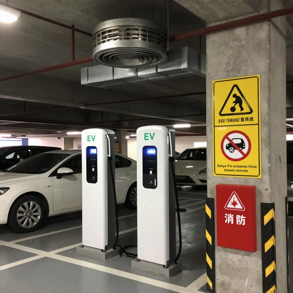
Why EV Charger Spacing and Smoke Exhaust Capacity Get Planned Apart
In a mall parking garage upgrade, EV charger spacing and smoke extraction capacity usually arrive on two sets of drawings that nobody is required to reconcile. Electrical contractors place charger bays around cable reach and traffic flow. Mechanical engineers size exhaust fans and make-up air for the layout they were handed, which predates the chargers. The two sheets rarely meet on the same page.
That gap matters because parking garage fire control depends on both halves at once. Charger bays group cars more tightly and add ignition sources, so exhaust has to clear hot gas from wherever those clusters actually end up, not from where the original smoke model assumed they would be. Widen or shrink bay spacing without rechecking extraction, and the design quietly carries a fire load the system was never sized for.
The comparison below sets charger bay spacing against smoke extraction performance on the same deck: how bay layout shifts the smoke layer, how exhaust capacity responds, and why neither figure on its own tells you whether a fire strategy holds up in an incident.
When Bays Get Closer, Smoke Builds Faster
EV charger spacing looks like a layout decision. It is really a fire-behaviour decision. Group chargers into tight clusters to shorten cable runs and cut installation cost, and the gap between bays shrinks until vehicles sit almost nose to nose. Heat from one burning battery pack then has nowhere to go but into its neighbours, so the fire stops behaving like a single car fire and starts behaving like a row fire. That concentration lifts the heat release rate – the speed at which a fire gives off energy – and a faster fire produces smoke sooner, in larger volume, spreading across the ceiling more aggressively than a well-spaced layout would.
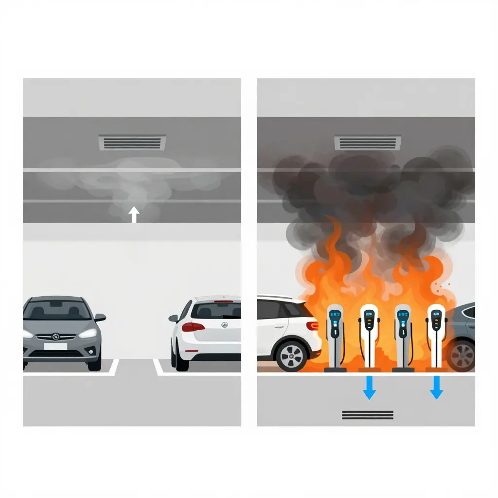
The three terms that carry the argument are simpler than they sound. The smoke layer is the blanket of hot, sooty gas that gathers under the ceiling; wide spacing lets it spread thin and stay high, while crowded bays push it thicker and lower, toward the height where shoppers walk. Make-up air is the outside air a garage must pull in so extraction fans have something to move, and a packed row of cars and chargers can block the paths that air needs. Air changes per hour is how many times the garage’s full air volume is swapped in an hour – the figure printed on compliance drawings, and the one most often carried forward unchanged when a layout changes.
The tension is that tighter spacing shifts smoke generation toward a faster, larger, denser volume, and that volume is exactly what the smoke exhaust capacity has to clear. Size the fans against an open, generously spaced layout and the two figures no longer match: the ceiling layer drops before people have finished walking to their cars. Run the charger layout and the smoke exhaust capacity as one calculation instead of two separate approvals. That is where the margin sits.
A nameplate airflow rating is not a protection level. The real smoke exhaust capacity of a garage is set by the whole system, and each of these parts can take flow away from the published figure:
- Extraction fan rating – the published airflow figure comes from a test under ideal inlet conditions, so any real-world restriction immediately eats into it.
- Duct routing and leakage – long, winding or poorly sealed duct runs lose air before it reaches the fan, shrinking performance without showing up on any gauge.
- Number and size of exhaust openings – too few or undersized grilles let hot smoke pool in corners instead of being drawn out evenly across the deck.
- Make-up air path – a system can only remove what replacement air allows in, so blocked or undersized intake routes choke the whole operation.
- Ceiling height and clear smoke layer – a taller slab holds the smoke layer above people’s heads longer, buying escape time a low deck cannot offer.
- Compartmentation and smoke curtains – splitting the deck into zones stops smoke spreading sideways and lets the system concentrate on the fire area.
- Interaction with daily ventilation modes – if the routine CO-driven ventilation mode fights or overrides fire mode, the designed capacity never shows up when it matters.
- Maintenance and damper condition – sticky dampers, clogged filters and deferred service cut flow long before an alarm or inspection reveals it.
Charger spacing decides how much energy and how many vehicles sit inside a single zone, so it belongs in that list rather than arriving after the ductwork is fixed.
Charger Spacing Meets Smoke Exhaust: A Zone-by-Zone Comparison
The table below lines up typical EV charger spacing in each mall garage zone against the smoke exhaust capacity that zone usually has.
| Garage zone type | Typical EV charger spacing range | Smoke exhaust capacity characteristic | Primary risk when the two are mismatched | Recommended first action |
|---|---|---|---|---|
| Single-level open-deck garage | Wide, often 6 to 10 stalls between charger pairs | Passive cross-venting with light mechanical assist; naturally drafty and unpredictable | Smoke drifts sideways across the deck toward stair and lift cores before fans get a grip on it | Walk the deck on a windy day and sketch where smoke actually travels before adding posts |
| Enclosed basement level near mall entrances | Dense, chargers clustered within 2 to 4 stalls of lobby doors and lift banks | Moderate extraction with short duct runs serving the busiest pedestrian zones | A busy charging cluster sits right on top of the exit route shoppers rely on | Cap charger density at the entrance cluster and push a share of posts deeper into the level |
| Deep basement level with long duct runs | Medium, spread fairly evenly along long aisles | Extraction tapers with distance, so the far end of the level pulls noticeably weaker | Smoke lingers in remote corners while fans work the near side of the level | Test extraction at the farthest charger bay, not the one closest to the plant room |
| Loading and service bay zones | Irregular, posts squeezed between dock doors, ramps and turning circles | Extraction sized for short bursts of vehicle exhaust, not sustained charging activity | Blocked access for response vehicles plus uneven smoke capture around tall bodies | Re-check clearances and keep charger posts clear of turning envelopes and dock aprons |
| Mixed-use level shared with municipal or cargo vehicles | Sporadic, chargers sharing bays with larger fleet units of varying heights | Capacity built around passenger car profiles, so taller vehicles strain the design assumption | Taller bodies push smoke into the ceiling layer faster than the level was set up to clear | Review the actual vehicle mix and confirm height and clearance assumptions hold |
If your garage shares space with municipal fleet vehicles, the vehicle mix is usually the variable that shifts fastest, so it is worth revisiting before any charger expansion. Read each row as a starting point for a site walk rather than a verdict, and let the zone with the tightest fit set the pace for the rollout.
Setting the Baseline Before You Compare Anything
Before you weigh EV charger spacing against smoke exhaust capacity, pin down what each document actually promises. The fire code and the approved mechanical drawings state smoke exhaust capacity in air changes per hour for the garage, extraction volume per bay, and the aisle widths the original ventilation check assumed. The charger installation plan states the EV charger spacing, the mounting positions, and how long a single run of chargers may continue along a wall or island.
Pull the current stamped versions of both, note their revision dates, and copy the exact zone labels and grid references each one uses – corridors, ramps and dead-end pockets are routinely named differently on electrical and mechanical sheets. If the labels do not line up, you are not yet comparing the same garage zone.
Once the zones align, work through the four thresholds that matter most: air changes per hour across the whole zone, extraction volume per bay closest to the chargers, minimum clear aisle width that survives once bollards, signage and cable management are installed, and the maximum continuous charger run before the layout needs a break. Treat all four as questions rather than fixed numbers, because acceptable values shift with ceiling height, sprinkler design and local amendments. Confirm every figure with your local authority having jurisdiction and with the design engineer of record before you sign off, and keep their answers in writing alongside the drawings so the baseline stays defensible later.
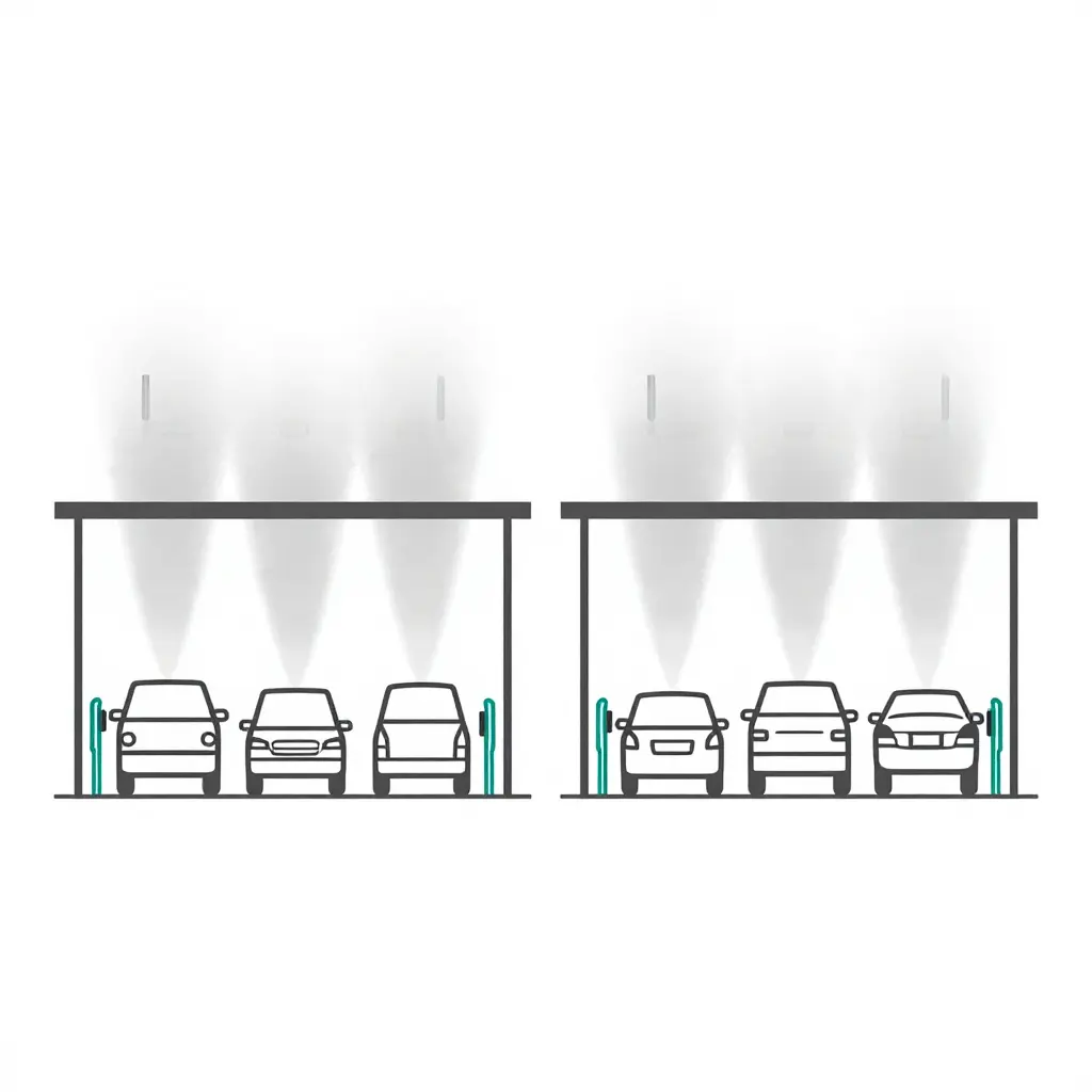
Figure note: The left section shows charging bays at generous intervals; the right section repeats the same bays at a tighter interval. Smoke accumulates as a horizontal layer under the ceiling and is drawn out through the extraction openings, while replacement air enters low at the far side and keeps the upward travel path that holds the occupied zone clearer.
Balancing Charger Density Against Exhaust Capacity
Adding chargers is the cheap half of the equation. Moving the air those chargers make necessary is not. A garage ventilated for petrol-era fire loads is typically sized on a design fire of a few megawatts, and lithium-ion vehicle fires burn longer, release more total energy and produce a different smoke profile than the fans, ducts and relief openings were commissioned for. Push more bays into the same footprint and you shorten EV charger spacing without changing the extraction rate: each fan runs longer at higher duty, energy bills climb for years, and the retrofit you skipped comes back as fan motor replacements, nuisance alarms and a compliance file that no longer matches the as-built layout.
Doing the extraction work first front-loads cost but stops the risk compounding. It usually means larger or additional exhaust fans, rebalanced supply and relief paths, new duct runs, and changes to existing openings and shafts – work that is disruptive, sometimes load-bearing, and frequently collides with the compartmentation strategy the building already relies on. Ventilation also decides what detection and suppression see: in a well-ventilated garage, smoke is diluted and travels along the intended paths, so beam detectors and sprinklers respond roughly as designed; in a starved or over-pressurised space, smoke migrates into lift lobbies and retail interfaces and suppression may not see the fire where it actually is. Expect phased works, night shifts and temporary bay closures during the programme.
Tenants and insurers read the same drawings you do. A tenant reviewing lease obligations will ask what changed about smoke exhaust capacity when the bay count changed; an insurer will ask how the new bays feed their fire model, and may answer with a premium adjustment, a condition or an exclusion. Because parking garage fire control is judged as a system rather than a list of components, upgrading extraction first gives you one coordinated account for both audiences. Estate and fleet support equipment belongs in the same maintenance schedule, among it the road sweepers that keep decks clear of combustible debris, so the ventilation system and the floor it protects are held to one standard.
Decision rule: If upgrading fans, ducts and openings costs less per added bay than the lifetime insurance premium and rent concession you would give away for an under-ventilated layout, upgrade extraction before you expand density. If it does not, cap charger density at what your existing extraction can clear at the design fire size, and revisit the question only after a measured airflow test.
Where Charger Growth Outpaces Exhaust Capacity
Before approving another row of EV chargers, put both numbers side by side: how densely chargers are installed (per 1,000 m²) and how much smoke exhaust capacity the zone can deliver against its design demand (as a percentage).
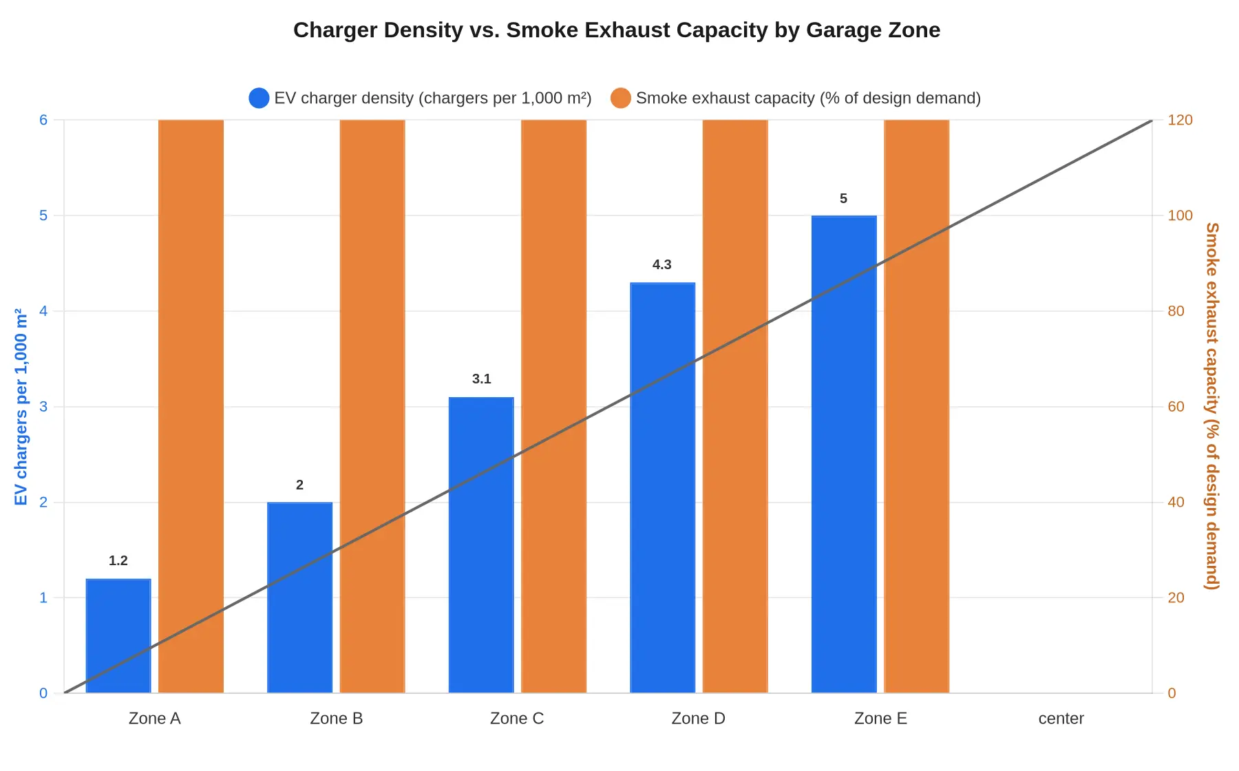
Illustrative planning data, not measured field data.
| Zone | Chargers per 1,000 m² | Smoke exhaust capacity (% of design demand) | Reading |
|---|---|---|---|
| A | 1.2 | 106 | Comfortable headroom |
| B | 2.0 | 99 | Roughly balanced |
| C | 3.1 | 93 | Drifting apart |
| D | 4.3 | 87 | Mismatch |
| E | 5.0 | 78 | Priority retrofit |
Takeaway: zones where charger density grows faster than exhaust capacity are the mismatch zones, and those are the areas to schedule for ventilation upgrades first.
Treat the crossover point as your planning signal. In this illustration it falls between Zone B and Zone C, where charger density keeps climbing while available capacity starts to fall – a pattern that shows up when EV adoption arrives faster than the original ventilation design assumed. The fix is rarely “add more fans everywhere.” It is usually zone by zone: shift charger placement toward well-ventilated bays, verify make-up air paths, and keep the deck clear so detection and response routes stay open. Routine parking structure cleaning equipment does that better than ad-hoc sweeping.
Commissioning, Monitoring, and Maintenance Routines
The link between charger spacing and extraction zones only survives if someone keeps testing it, writing it down, and rechecking it every time the garage changes.
- Capture the baseline at commissioning. Before the first vehicle plugs in, record every charger group with its kW rating, the extraction zone and damper that serves it, and the exhaust airflow measured under design conditions, so later readings have a fixed reference point.
- Test fans and dampers on a fixed cycle. Run each exhaust fan and stroke each damper on a set schedule (quarterly for fans, twice yearly for dampers), confirming full travel, clean end switches and airflow within tolerance of the original figures.
- Verify detectors and the alarm sequence. Test smoke and heat detectors zone by zone and confirm the signal starts the correct fan group and damper response – not just a bell at the panel.
- Re-inspect after every fit-out. Walk the deck after any tenant works, signage install or storage change to check that exhaust openings are still clear and that aisles around chargers have not been narrowed.
- Log each charger addition. Keep a one-page register of new chargers – group, install date, kW – so the smoke exhaust capacity comparison is recalculated before the next wave of chargers is approved.
One named person should own that record, typically the facilities or fire safety officer, rather than a shared folder nobody claims. A copy belongs with the mall’s fire safety manager, reviewed annually and updated in the same week as any change, because a parking garage fire control programme lives or dies on whether that file is current.

The diagram reduces the work to four steps: inventory where the chargers actually sit, map the extraction zones that serve those areas, set the two data sets against each other, and reach a decision point that splits two ways. One branch says the layout works as it stands. The other flags an area where charger spacing and exhaust coverage pull in opposite directions and needs attention before the next tenant moves in.
Fleet and Service Vehicle Access in Shared Garage Levels
Mall parking levels are rarely passenger-car only. Facilities teams run utility trucks, cleaning machines, waste-handling vehicles and light cargo units through the same decks during off-hours, and outside contractors bring their own equipment in as well. Every one of those vehicles reshapes the aisle geometry, which changes how many EV chargers you can realistically space across a level. For fire control planning that is not a side issue: charger count per deck feeds directly into the heat release rate your smoke exhaust system has to handle.
Which vehicle classes actually change the layout
- Light cargo and box-body vans delivering to service corridors, with body widths and door swings that eat into charger-adjacent clearance.
- Road sweepers and scrubbers used for overnight cleaning, which sweep wide arcs and need extra room at corners and column lines.
- Solid-waste collection vehicles transferring from bin rooms, where reversing envelopes are the real constraint.
- Tow trucks and flatbeds responding to disabled vehicles or failed chargers on the deck.
- Utility and maintenance pickups carrying ladder racks, lifts or mounted equipment that raises effective height and side clearance needs.
Dimension checks to request
Ask the fleet or facilities lead for these figures in writing, not verbally at a site walk:
| Vehicle class | Check that affects charger spacing |
|---|---|
| Light cargo / box-body van | Overall width including mirrors, rear door swing |
| Road sweeper / scrubber | Curb-to-curb turning radius, sweep arc at columns |
| Solid-waste loader | Reversing envelope, bin room approach width |
| Tow truck / flatbed | Rear overhang, boom clearance, ramp approach angle |
| Utility pickup | Height with rack, side clearance at charger pedestals |
Also request operating hours and the peak number of service vehicles expected on a level at once. Two sweepers passing each other at 5 a.m. is a different constraint than one van at noon. With those numbers in hand, compare them against the charger layout: aisle width, turning clearance at ramp transitions and column setbacks typically cut the number of bays you can fit, and pushing chargers closer to turning paths usually costs more in bollards and repair than it saves in count. Fewer, correctly spaced chargers often fit your existing exhaust capacity better anyway.
FAQ
Does adding more chargers always mean you need more exhaust capacity?
Not automatically. What matters is how the added load changes the worst-case fire scenario the system is designed for, not the raw number of charging points. A tight cluster of high-power units in an enclosed corner can stress a garage far more than several lower-power units spread across a wide, well-ventilated level. Exhaust capacity should follow the scenario, not the headcount.
How often should the spacing-to-capacity comparison be repeated?
Whenever the layout or the equipment mix changes, and at minimum as part of your routine fire-safety review cycle. Treat the comparison as a document that gets maintained, because EV charger spacing and exhaust performance drift apart quietly as tenants install, upgrade or relocate units.
Can existing extraction openings be reused?
Often yes, but verify rather than assume. Confirm that the openings still sit where hot smoke will collect once the new charger layout is in place, and that their size and distribution match the scenario you are now designing for. Reuse is a perfectly valid outcome; reuse without verification is not.
What should we do when a level is fully occupied but chargers must be added anyway?
At that point the comparison becomes a constraint-solving exercise rather than a pass-or-fail check. You can redistribute charger positions to reduce clustering, split the charging load across levels, or phase the rollout so exhaust upgrades land before the additional units go live. Document the trade-offs you accept so the decision is defensible at the next inspection.
Which document set should the comparison be based on?
The approved, as-built drawings together with the current equipment schedule – not leasing plans or the original design intent. If those sources disagree, resolve the discrepancy first, because EV charger spacing figures quoted from an outdated drawing give you a false sense of compliance and hide real gaps in smoke exhaust capacity.
Conclusion
Parking garage fire control is one engineering problem, not two line items. A charging layout decides where heat and smoke will start; the exhaust design decides whether that smoke can be cleared off the deck. Reviewed separately, each can look compliant while the pair fails together. Reviewed on the same drawing, they answer both questions before anyone commits to concrete, conduit or fan sizing.
Comparing the two on paper is a low-cost document exercise: a few drawings, a ventilation calculation, and a short review with your fire protection engineer. That is inexpensive next to the alternative – retrofitting exhaust capacity or moving charger positions after the garage is built and cars are already parked in it. It is worth doing because it catches a mismatch in week two rather than year five.
Three actions to assign this quarter:
- Commission a one-page overlay drawing that plots charger positions against exhaust zones.
- Ask your fire protection engineer to confirm smoke exhaust capacity against the planned charger count in writing.
- Name one person to record the review date and file the drawing with the garage’s fire documentation.