

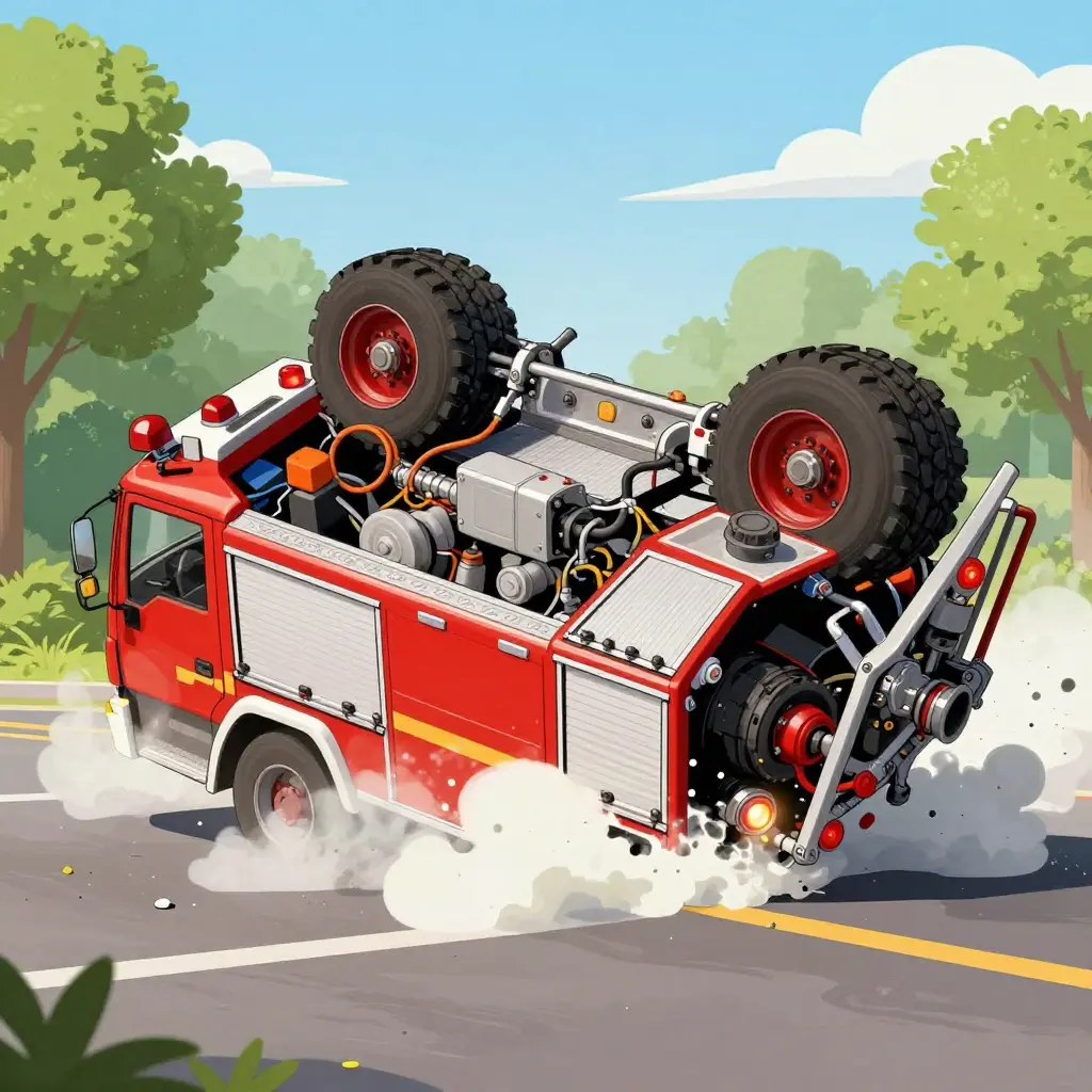
Fire Truck Rollovers: A Compounding Failure, Not a Single Cause
Fire apparatus rollovers are rarely the result of one bad decision by a driver. The cases that repay close analysis usually involve two mechanical effects at the same time: liquid surge inside the tank and brake fade. Each degrades stability through its own physics, and where the two overlap they drive the uneven weight transfer that ends in a rollover. Blaming driver error alone hides the engineering chain that a rollover scene reconstruction is meant to document.
A fire truck carrying a partial load of water does not behave like the vehicle its axle-weight ticket describes. A baffled or unbaffled tank is a moving mass, and its center of gravity slides sideways during cornering and braking and shifts under grade changes. At the same time, hard braking on a descent heats the friction surfaces, lowers the coefficient of friction, and stretches stopping distance just when the driver is asking for the most deceleration the vehicle can give.
The sections below follow that argument in three steps: how liquid moves inside a partly filled tank, how heat degrades heavy-duty brakes, and how the two combine into a reconstruction method that can be checked against scene evidence. Apparatus built on commercial municipal chassis platforms matter here, because their braking and suspension hardware is often shared with chassis designed to carry liquid loads with a smaller roll moment.
Tank Surge: The Physics of Moving Liquid Mass
The heaviest thing on a fire truck is often the mass you cannot see moving. Tank surge is the transient redistribution of liquid inside a partly filled tank, and it changes handling in ways a static axle-weight ticket never captures. Get the slosh dynamics wrong in a reconstruction and the analysis becomes an educated guess.
Apparent stability is not real stability. A truck that passes a curb-weight check can still be close to rollover the moment the water starts to move.
Longitudinal and Lateral Slosh
Two motions carry the load transfer. Longitudinal slosh runs fore and aft under braking and acceleration; lateral slosh runs side to side in a corner. Each oscillates at its own natural frequency — roughly 0.3 to 0.7 Hz for fire apparatus tanks — set by tank geometry and fill depth. When driver or road inputs hit that frequency, resonance amplifies the motion quickly.
The Free-Surface Effect and Center-of-Gravity Migration
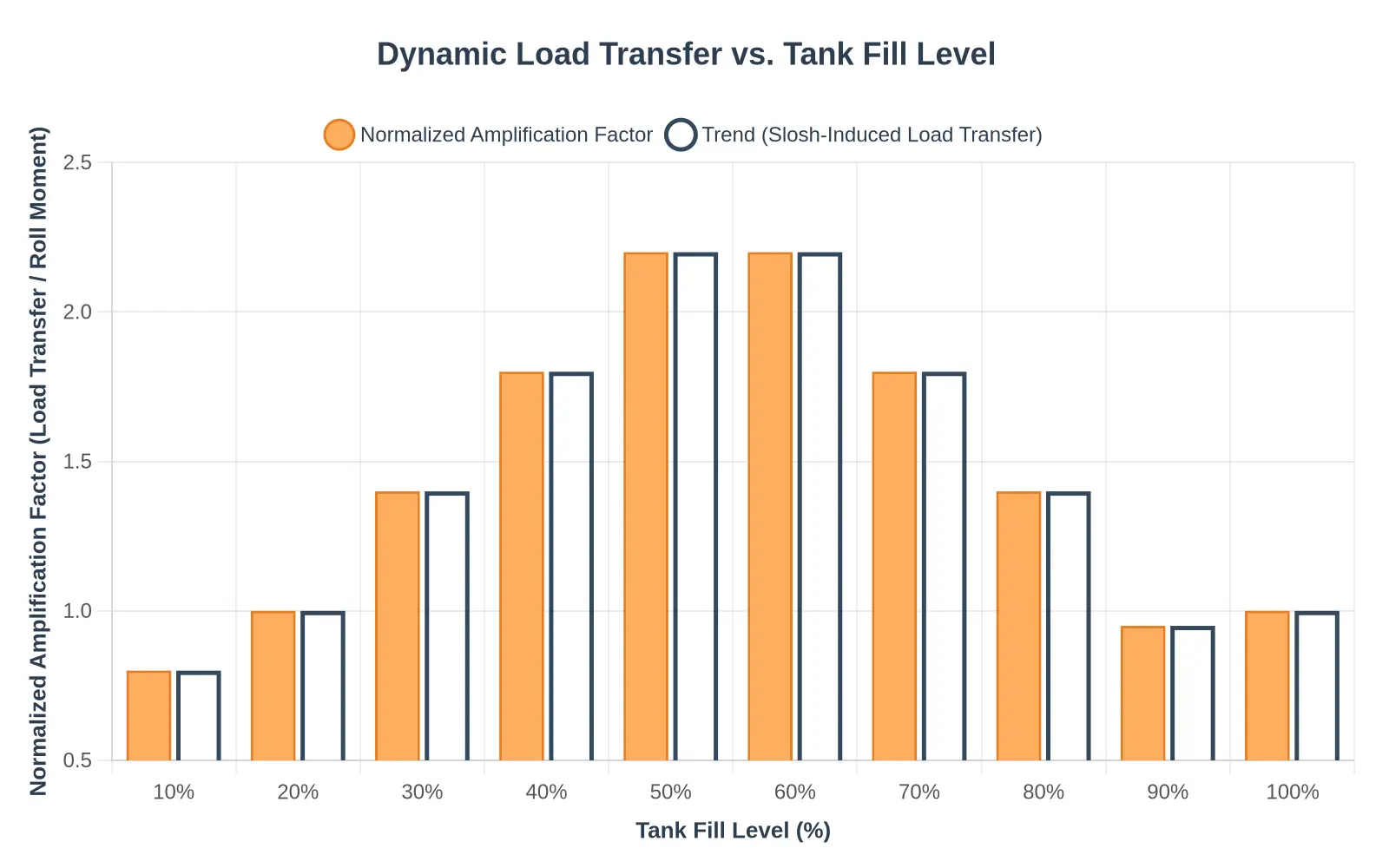
Any liquid with a free surface is a moving mass. As fluid rises on one side, the center of gravity moves toward that side and upward, because the effective CG of a swaying liquid rides higher than the static one. The void above the liquid, the ullage, grows with every partial fill and gives the surface more room to travel. That is why a tank at 50 percent is often more destabilizing than one at 95 percent.
Why Partial Fills Amplify Load Transfer
Dynamic load transfer does not peak at a full tank. It peaks in the mid-fill range, where the free surface has the most room to translate. Under hard braking, the surge adds a longitudinal force that pitches weight onto the front axle; in a corner, the same mass swings sideways and increases the roll moment, the torque that rotates the vehicle about its longitudinal axis. Baffles split the tank into compartments to raise slosh frequency and damp amplitude, but their effectiveness depends on how many there are, where they sit, and how much perforation area they have. For anyone specifying liquid-hauling tanker configurations, that is a design constraint as much as a handling one.
The Implication for Rollover Risk
Combine a mid-fill tank with brake fade and the margins disappear. The slosh-driven roll moment adds to reduced braking authority, which lowers the threshold at which the truck rolls. A reconstruction that ignores the moving liquid mass will understate that roll moment and undermine the rest of the analysis.

The diagram above isolates the mechanism behind many apparatus rollovers. In a partly filled tank the water’s free surface is not rigidly coupled to the chassis, so its mass redistributes whenever the truck decelerates or turns: under braking it rushes forward as a longitudinal surge, and in a corner it sloshes laterally against the tank walls. The combined center of gravity migrates with it instead of staying fixed. On a fire truck, where the tank sits high above the axle line, even a modest lateral shift raises the effective center of gravity and lengthens the roll moment arm. Add brake fade on a downgrade — reduced retardation delays load transfer and encourages a higher entry speed into the curve — and the two effects compound. The schematic illustrates that interaction for forensic and fleet work; it does not depict any particular incident.
Brake Fade Under Emergency Response Loads
In most heavy-vehicle rollover reconstructions, the decisive question is not whether a brake broke but whether it quietly stopped delivering torque before the driver noticed a loss of control. Thermal brake fade — the progressive loss of braking torque as friction surfaces overheat — turns a serviceable system into a hazard without leaving fractured hardware behind. Because it develops gradually and depends on temperature, it is easy to mistake for a sudden catastrophic failure in post-incident analysis.
A brake turns kinetic energy into heat at the friction interface, and the assembly has to absorb that energy in its thermal mass before it can shed it to the surrounding air. Repeated hard stops, exactly what an emergency response at elevated gross vehicle weight produces, deposit heat faster than the drum or rotor can reject it. As lining temperature climbs, the coefficient of friction falls, so braking torque drops even though pedal force has not changed.
Drum and disc designs fail that test differently. Enclosed drums carry a large thermal mass and resist a single hard application, but they trap heat and fade badly once saturated. Ventilated discs run cooler and recover quickly, though their lower mass leaves them exposed to rapid successive stops. The table below contrasts the two, and the chart tracks how retained torque diverges across a stop sequence.
| Attribute | Drum Brake | Disc Brake |
|---|---|---|
| Heat dissipation | Enclosed; sheds heat slowly | Ventilated; sheds heat quickly |
| Thermal mass | High; resists a single hard stop | Lower; prone to successive-stop fade |
| Fade onset | Late but severe once saturated | Earlier onset, faster recovery |
| GVW sensitivity | Amplified on heavy fire apparatus | Amplified on heavy fire apparatus |
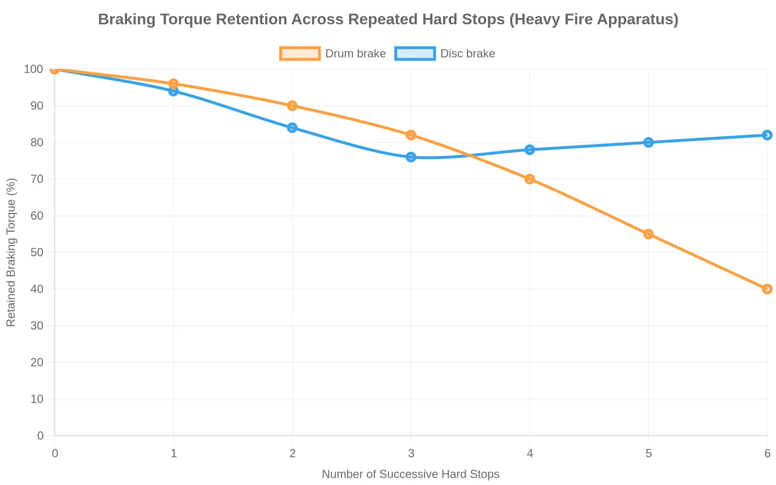
Multipliers matter as much as hardware. Braking torque requirements scale with gross vehicle weight, and the heat produced in each stop scales with the square of speed and directly with mass. Teams specifying municipal fleet braking configurations face the same physics that reconstruction engineers work through after a crash. On a fire apparatus running near its GVW ceiling, a short series of hard stops can push retained braking torque toward half its cold value, and stopping distance grows with it — often by 40 to 60 percent. That difference is what separates a controlled stop from a rollover entry.
In reconstruction, brake fade belongs in the model as a predictable thermal state, not an intermittent defect. Establish the gross vehicle weight at the moment of the event, reconstruct the number and severity of the preceding hard stops, then calculate the retained braking torque each brake could still deliver. Only once fade is separated from outright mechanical failure can stopping distance, and the role it played in the rollover, be defended with confidence.
Brake System Comparison for Fire Apparatus
Brake fade is one of the most consequential and least visible variables in a fire truck rollover reconstruction. When a loaded apparatus descends a grade with a charged tank, the foundation brakes absorb kinetic energy well beyond their design envelope, and how fast that energy dissipates decides whether stopping torque survives the descent. What an investigator can actually measure is the friction pair, not driver intent, so the table below compares the three foundation systems most often found on fire apparatus. The aim is to line up physical evidence — drum scoring, rotor crazing, boiled fluid — with the fade behavior each configuration should show.
| Parameter | Drum Brakes | Disc Brakes | Air-over-Hydraulic |
|---|---|---|---|
| Heat dissipation capacity | Moderate; heat trapped inside the closed drum sheds slowly | High; vented rotor releases heat rapidly to airflow | Moderate to high; governed by the foundation brake used |
| Fade onset temperature | Lower; roughly 400-500 deg F (205-260 deg C) | Higher; roughly 600-800 deg F (315-425 deg C) | Intermediate; hydraulic fluid boil sets an extra ceiling |
| Recovery time | Slow; often several minutes before full torque returns | Fast; typically seconds to about one minute | Moderate; limited by fluid and drum/rotor cooling |
| Maintenance sensitivity | High; shoe clearance, return springs, and drum scoring all degrade output | Low to moderate; pad and rotor wear is visually inspectable | High; both air and hydraulic circuits require disciplined service |
Reading the Table Against Physical Evidence
A few cues help anchor the reconstruction. Drum brakes with heavy heat checking and slow torque recovery point to the lower fade threshold and sluggish heat shedding in the second row — a pattern that lengthens stopping distance on sustained downgrades. Disc systems tolerate a higher fade onset and recover quickly, so an apparatus equipped that way rarely shows the same runaway signature unless fluid or pad condition has degraded.
Air-over-hydraulic arrangements deserve particular attention because they carry the maintenance sensitivity of two stacked systems. One neglected hydraulic seal or air-line leak can erode both recovery time and the fade ceiling, narrowing the safety margin before a rollover. Investigators documenting fleet-level patterns can compare these platforms across municipal service vehicles to judge whether a failure was anomalous or systemic.
When Surge Meets Fade: The Coupled Rollover Mechanism
Brake fade and liquid tank surge are each hazardous on their own. In the same braking event, though, they do not simply add — they multiply. That coupling is what explains how a fire apparatus rolls on a corner it looks, on paper, able to take.
Chain One: Fade Lengthens the Stopping Window
Start with the brakes. Prolonged, repeated, or heat-soaked braking causes brake fade: friction material loses coefficient, drums and rotors overheat, and deceleration falls off. The practical result is a longer stopping distance, a stretched stopping window that keeps the rig moving faster than the driver intended and exposes it to lateral acceleration from the corner for more time, not less.
Chain Two: Surge Moves the Center of Gravity
Then add the tank. A partly filled water or foam tank does not act like a rigid mass. Under braking and cornering, the liquid tank surge shifts the free surface, moving the vehicle’s combined center of gravity (CG) laterally toward the outside of the turn and forward toward the steer axle. Because the fluid on a fire apparatus can be a large share of gross vehicle weight, that CG migration is substantial rather than marginal.
Where the Two Chains Converge
The coupling is the problem:
- Fade stretches the stopping window and holds the rig in the corner longer.
- Surge pushes the CG laterally and forward during that same window.
- Longer exposure amplifies the lateral CG offset, because the fluid keeps sloshing while the truck keeps cornering.
- The two combine into a single roll moment about the outside tires.
Crossing the Rollover Threshold
Every chassis has a rollover threshold: the lateral acceleration at which the overturning moment overcomes the restoring moment from track width and CG height. A high-GVW platform with a tall, fluid-laden body starts with a lower threshold. Weight distribution on a heavy commercial chassis matters here — forward-biased, high-mounted loads raise the vertical CG and shorten the effective rollover margin. When fade and surge combine, the roll moment can cross that threshold before the driver has any chance to unwind the steering.
Reconstruction therefore treats the two phenomena as one coupled mechanism rather than two separate findings. The same loading logic governs any high-GVW platform, such as the dump truck range designed for heavy chassis payloads, where partial loads and hard braking produce comparable CG migration and roll-moment amplification.
Reading the Fade Curve
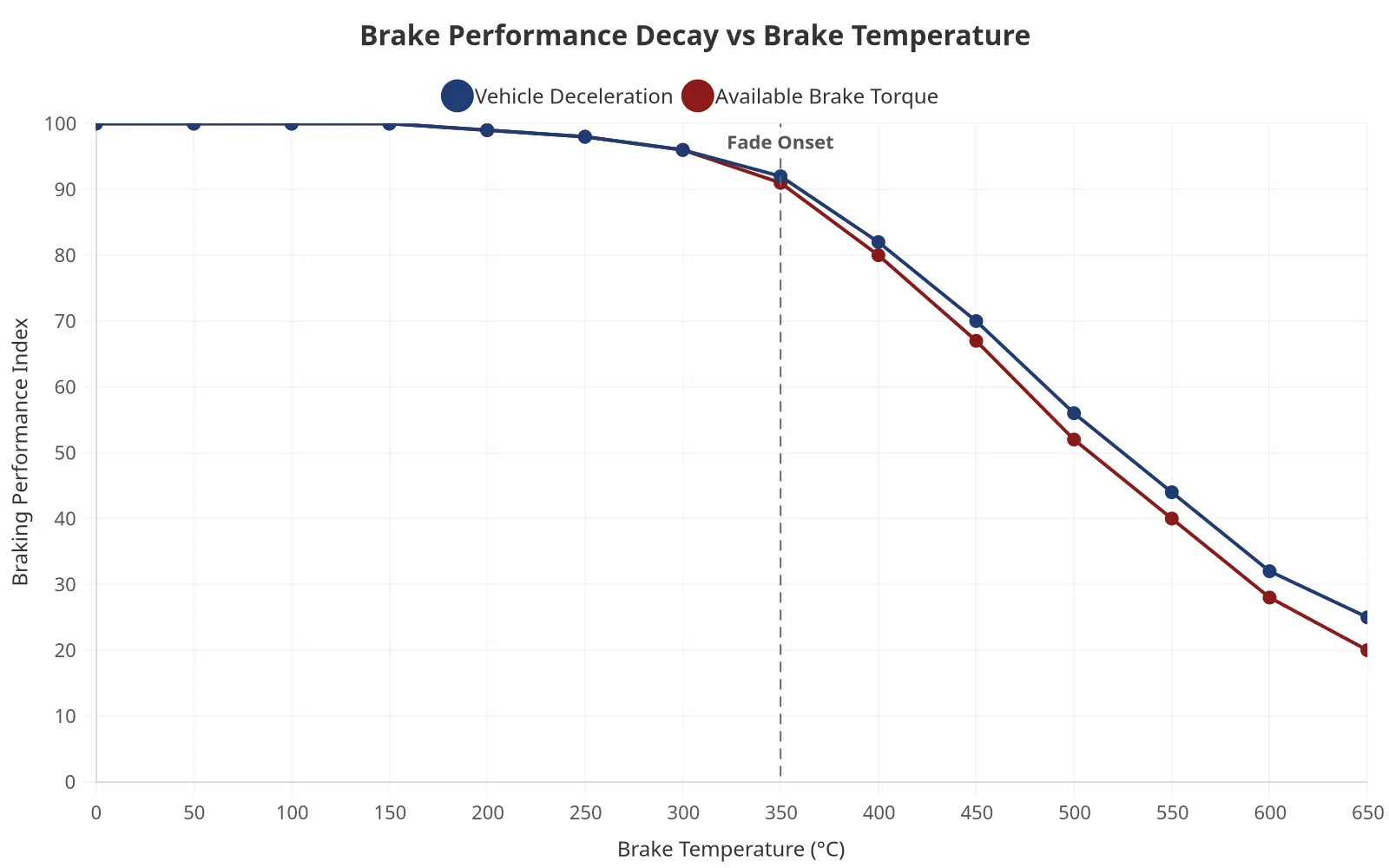
The chart isolates one of the most consequential variables in a fire truck rollover investigation: thermal brake fade. Below roughly 300 °C, both series stay flat and stable — the regime drivers see during normal service braking. The curves begin to separate only once the friction material can no longer shed heat as fast as braking generates it.
The inflection is the story. At the fade onset point (≈350 °C), the slope of both curves changes abruptly: vehicle deceleration and available brake torque, which had tracked each other closely, both fall into a steeper decline. By 650 °C, deceleration is down to roughly a quarter of its cold baseline, and available brake torque has eroded further.
That compression of the timeline is what matters for reconstruction:
- Below 300 °C — predictable performance; pedal force maps to expected retard.
- Around 350 °C — fade onset; the driver’s habitual braking input no longer produces the same retard, often with no obvious pedal-feel warning.
- Above 500 °C — steep degradation; stopping distance grows sharply and the vehicle may no longer hold a downgrade.
Deceleration and torque decay are not linear, so a single point reading misleads. The temperature history of the run has to be paired with road geometry and load dynamics to build a defensible cause-and-effect sequence.
Reconstruction Evidence Checklist
- ECM and ABS event logs — pull raw pre-crash, crash, and post-crash frames before the unit is decommissioned
- Brake temperature sensor traces — preserve full thermal profiles to confirm fade onset and recovery
- Tank level and slosh sensors — document fluid motion timing against liquid-hauling tanker design and baffle configuration
- Yaw-rate sensor data — establish the exact moment of rotation onset and stability loss
- Lateral acceleration records — quantify cornering forces against the rollover threshold
- Tire marks — photograph, measure, and map skid, scuff, and scrub patterns on scene
- Electronic stability control (ESC) intervention records — verify actuation timing, duration, and which wheels braked
- Driver steering and throttle inputs — extract commanded vs. actual response from the data bus
- Gross weight and axle load documentation — reconcile loaded mass with placarded ratings
- Environmental and sightline evidence — log grade, cross-slope, surface friction, and drift conditions
Each entry should be synchronized to a common clock so surge, fade, and yaw events can be correlated frame by frame. Treat every data channel as perishable: download it once, hash it, and archive it before any shop teardown begins.
Reconstructing the Rollover Scene: A Data-Fusion Approach
No single stream of evidence fully explains why a fire apparatus rolls. Reconstruction treats the event as a system in which roadway geometry, vehicle dynamics, and the moving mass of water in the booster tank interact under braking. The method below fuses three independent datasets so competing hypotheses can be tested instead of asserted.

Testing the Hypothesis
The governing hypothesis is that tank surge and brake fade act together. Brake fade erodes deceleration authority late in the stopping sequence while longitudinal liquid surge shifts the center of gravity forward and adds a destabilizing pitch moment. Neither mechanism alone reproduces the observed yaw and roll signature; their coupling can.
Supporting Evidence
Physical evidence anchors the reconstruction. Yaw marks, tire scrub patterns, rollover furrow geometry, and post-crash damage fix the pre-trip speed, steering input, and roll direction.
Sensor data supplies the time history. ABS wheel-speed channels, IMU yaw-rate and lateral-acceleration traces, GPS trajectory, and tank-level sensors establish when braking degraded and how the fluid mass migrated.
Simulation closes the loop. Multibody packages such as PC-Crash and HVE model brake torque decay and liquid slosh, then iterate parameters until the simulated kinematics converge on the physical evidence.
Testing Joint Causation
Where the three streams converge, joint causation holds; where they diverge, an alternative mechanism is rejected. The same fused workflow transfers to any municipal emergency and utility vehicle platform whose dynamic response depends on coupled fluid and braking behavior.
Contributing Factors to Fire Truck Rollover Incidents
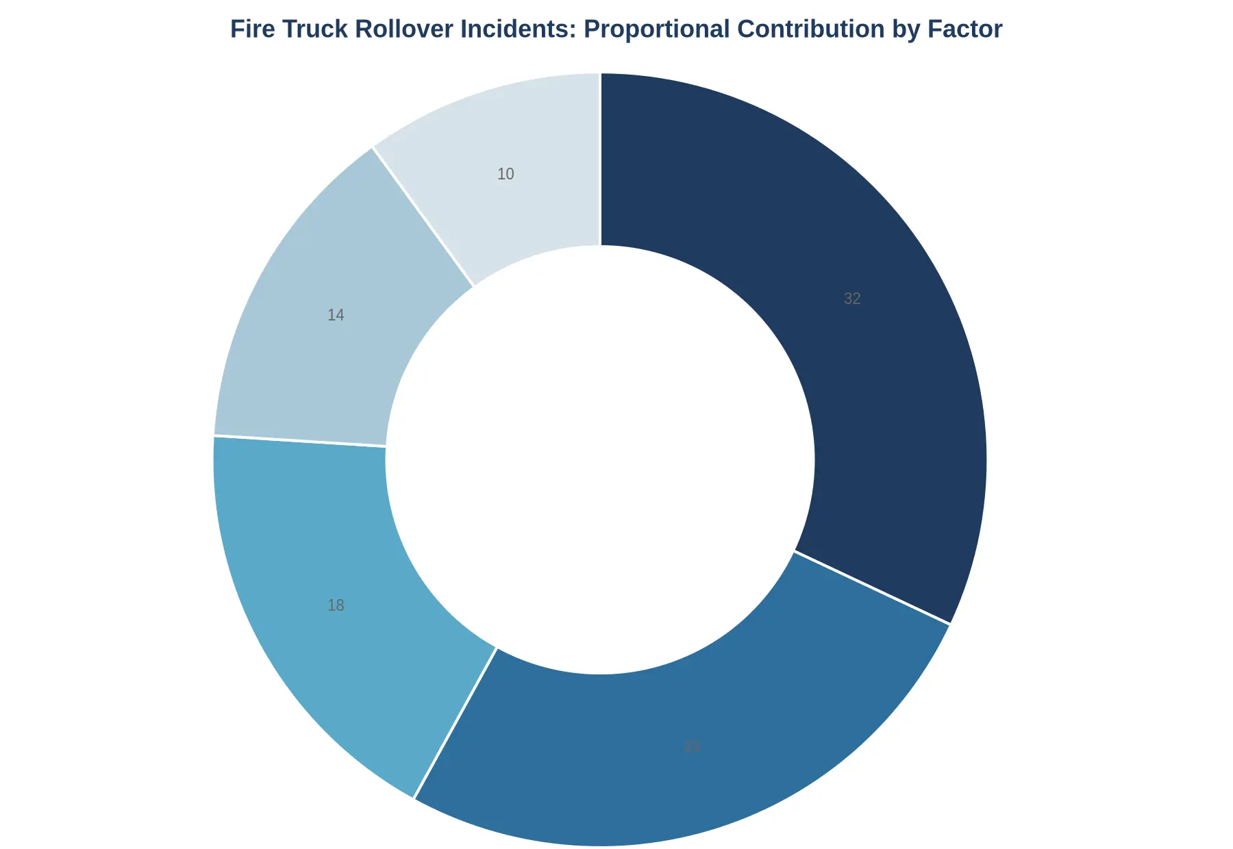
The chart assigns relative weight to the factors below: excessive speed 32%, tank surge 26%, brake fade 18%, road geometry 14%, and load distribution 10%. Speed and surge together account for more than half the total, which is consistent with how fluid movement interacts with vehicle velocity during evasive maneuvers and cornering. Brake fade and road geometry make up most of the remainder, and load distribution, though the smallest single segment, usually acts as a multiplier on the others rather than a trigger on its own.
Frequently Asked Questions
How do baffles mitigate tank surge in fire apparatus?
Baffles divide a partly filled water tank into smaller compartments, raising the liquid’s natural frequency and damping free-surface oscillation. By restricting how far water can slosh during braking or cornering, they reduce the dynamic load transfer that shifts the effective center of gravity and destabilizes the chassis. In reconstruction, engineers compare baffle geometry and compartment count — the same principles behind robust baffled liquid-tank designs — against the surge amplitude implied by the physical evidence.
Can brake fade be distinguished from brake failure after an incident?
Yes, but rarely from physical damage alone. Fade is a thermal phenomenon: friction material outgasses and loses coefficient of friction after repeated hard applications, so reconstruction relies on brake temperature models, duty-cycle data, and drum or rotor heat discoloration rather than a single fractured component. A mechanical failure, by contrast, typically leaves discrete failure morphology such as a sheared caliper mount or ruptured line that the investigator can date to the impact sequence.
How does simulation validate a coupled-failure theory?
A coupled-failure theory holds that two mechanisms — such as surge-induced load shift and thermally degraded braking — interact to produce the rollover. Engineers encode each mechanism in a multiphysics model, calibrate it against known vehicle parameters and event data recorder traces, then test whether the combined scenario reproduces the observed yaw, roll angle, and impact configuration. If the coupled model matches physical evidence better than either mechanism acting alone, the theory gains quantitative support.
Why is partial tank fill more dangerous than a full tank?
Water inside a partly filled tank can travel the length of the compartment and build surge forces that a full tank cannot, because there is nowhere for the liquid to go. The free-surface effect raises the center of gravity dynamically and can amplify roll during evasive maneuvering. Reconstruction must therefore establish fill level at the time of the incident, often inferred from witness accounts and residual fluid distribution.
What evidence best supports a tank surge hypothesis?
The strongest support combines physical traces with dynamic modeling. Investigators examine baffle condition, fluid staining patterns, and post-impact water distribution alongside wheel-speed and steering data to infer when surge forces peaked relative to steering input. Correlating these timestamps builds a defensible timeline linking liquid motion to the loss of control.
Conclusion: Engineering and Procedural Takeaways
Reconstructed fire truck rollovers rarely turn on a single failure. The dominant mechanism is coupled: tank surge shifts the center of gravity and lateral load transfer at the same moment brake fade erodes the retarding force the driver is counting on. The two effects compound, and the resulting yaw-and-roll sequence cannot be explained by either factor alone.
For apparatus design, that coupling argues for treating tank, chassis, and braking system as one dynamic unit rather than separate specifications. Baffle specification deserves particular attention: compartment geometry, baffle count, and fill level together govern how aggressively the liquid mass migrates during transient maneuvers, so baffled liquid-hauling tank design should be validated against the maneuvers an apparatus will actually perform.
Brake system selection should be benchmarked against realistic descent and panic-stop duty cycles rather than laboratory single-stop tests, so thermal capacity is sized for genuine brake fade risk.
Training should equip operators to recognize the early signature of surge and fade and to prioritize load stabilization over aggressive braking. Across design, specification, and procedure the takeaway is the same: manage surge and fade as a coupled threat, not as two separate problems.