

The Real Limit on Pump-and-Roll Flow Duration
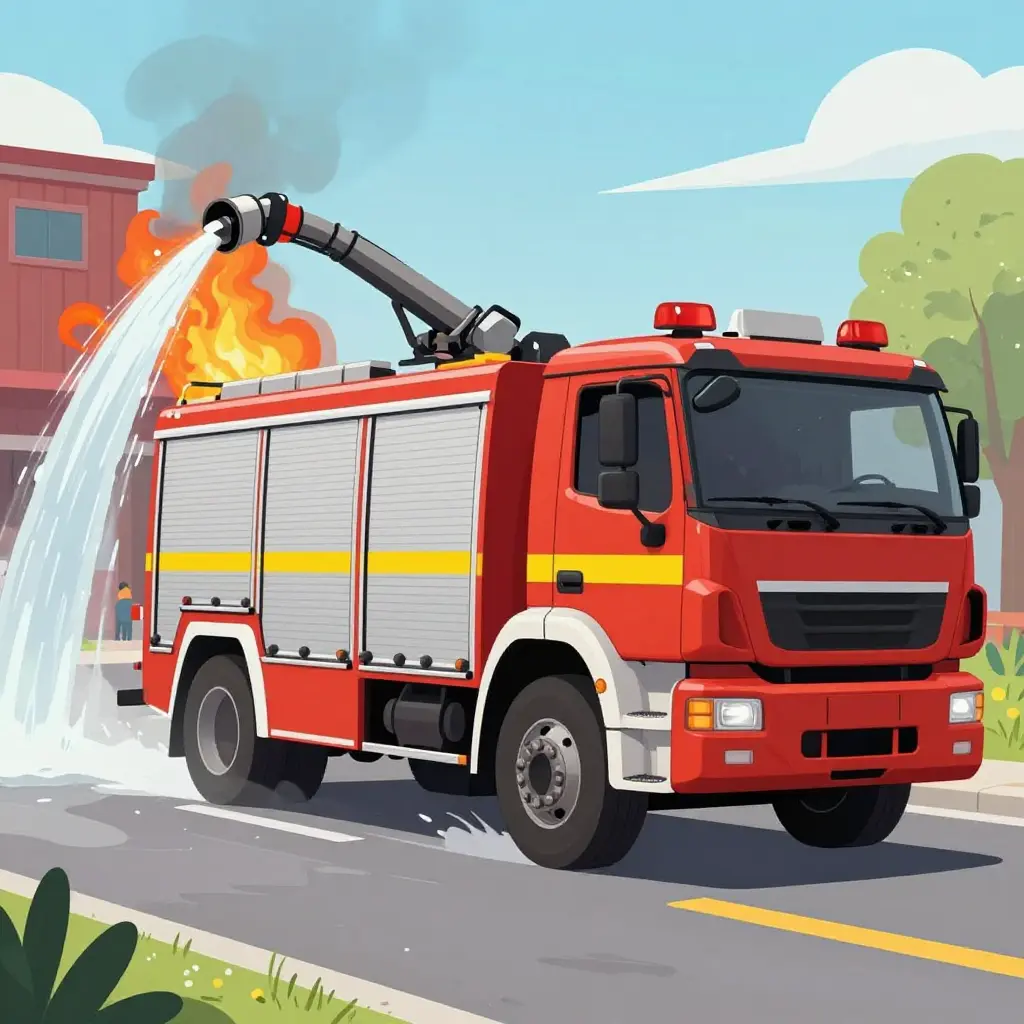
Pump-and-roll means discharging water through the pump while the apparatus is still moving. A truck pumper doing it is usually supporting attack lines, filling a portable tank, or keeping a water shuttle fed at a rural or wildland-interface fire with no hydrant nearby. Mobile water supply is the larger job of hauling water to the scene; pump-and-roll is one way a pumper keeps delivering it without stopping.
For the crews on the line, how long that water lasts decides everything: how long an attack can be held, whether a dump site stays supplied, and when the incident turns defensive.
Operators have long treated engine rpm as the performance dial, on the assumption that more rpm brings more pressure and more time on the water. On a truck pumper drawing from its own tank, that assumption fails. The ceiling on sustainable flow comes from the tank-to-pump line and its hydraulic resistance, not from how fast the engine turns.
How Pump-and-Roll Sustains Flow on the Move
Pump-and-roll turns a pumper into a temporary water source rather than a stationary engine. The fire pump is driven off the truck’s driveline through a split-shaft or PTO arrangement, so the impeller keeps turning and keeps building pressure even as the wheels roll. That continuous mechanical input lets water flow the moment the throttle is set.
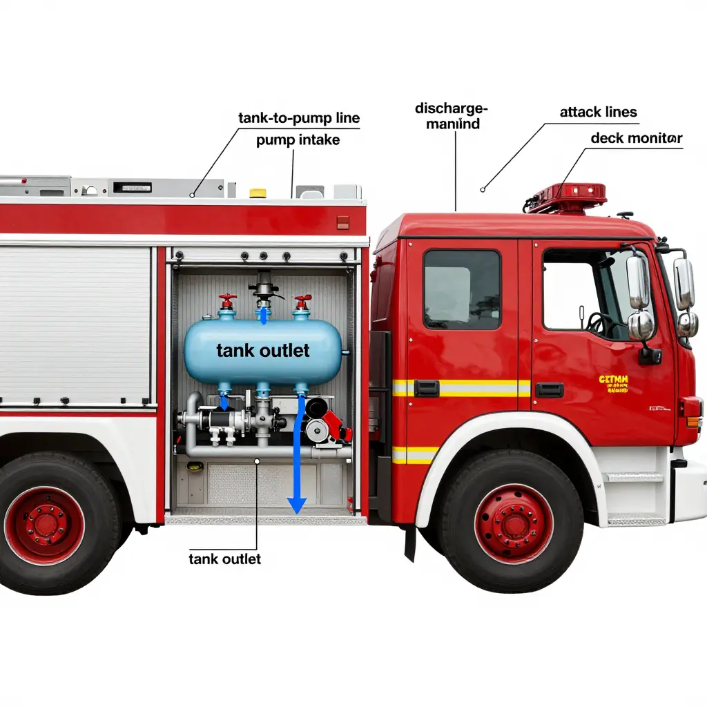
The water path is fixed and sequential. It starts at the tank outlet, a low-point fitting on the booster tank, placed so gravity helps the draw. Water then moves through the tank-to-pump line, a dedicated pipe sized to feed the pump at the rate the impeller can accept. Because the outlet sits low and the spinning impeller creates a slight vacuum at the pump intake, water is pulled through that line, not pushed. Once primed, the pump converts driveline rotation into hydraulic pressure and sends it into the discharge manifold, where valves route it to attack lines or a deck monitor.
The system is cause and effect. The tank-to-pump line sets the supply ceiling: if it is undersized, the pump cannot pull more water than the pipe delivers. Opening the throttle then just spins the impeller harder against a starved intake, pressure falls, and the stream stalls. Correctly sized plumbing is what extends how long a pumper can flow while rolling. The same hydraulic limits shape purpose-built liquid-handling apparatus, such as these municipal liquid-hauling platforms.
The Water Path, Step by Step
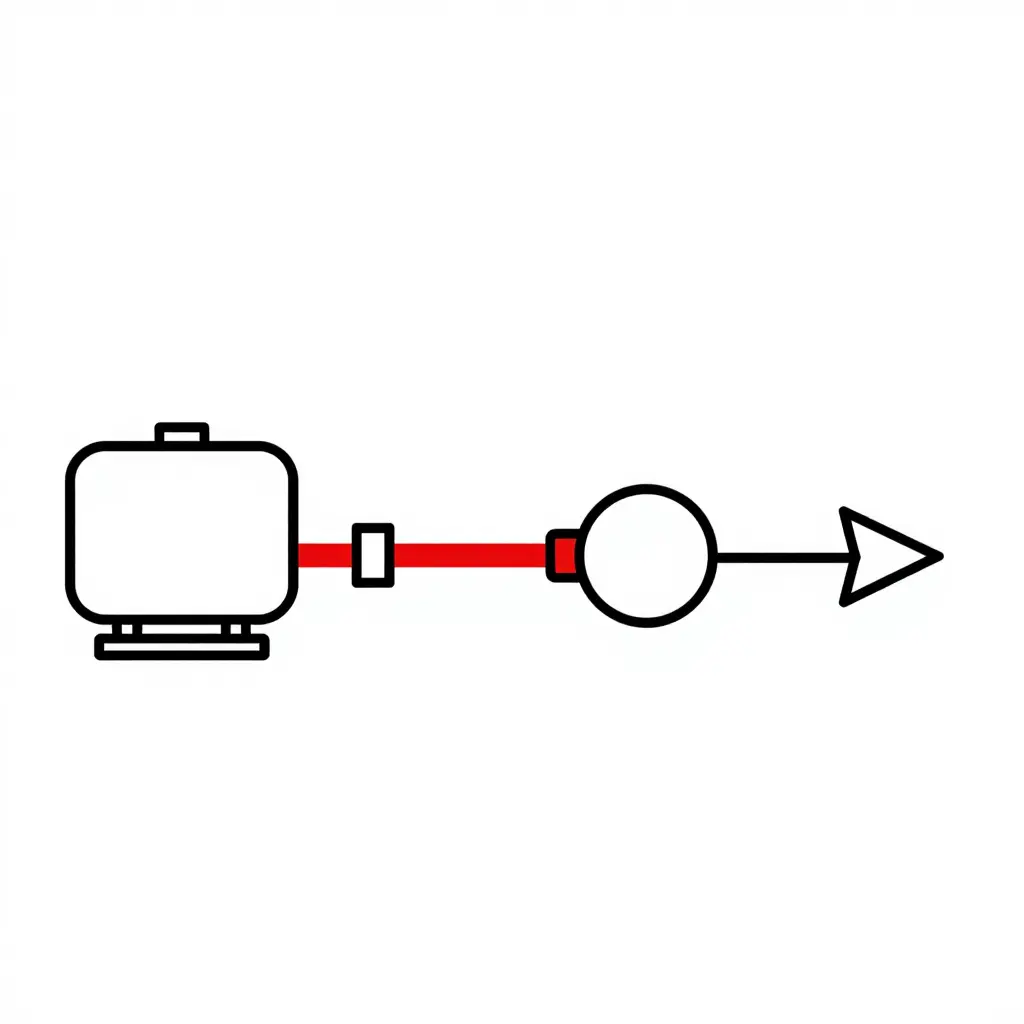
Read the schematic as one path. Follow it once and the bottleneck is hard to miss:
- Tank – the onboard water supply.
- Tank-to-pump line – the short suction run from tank outlet to pump inlet. It carries the heaviest stroke in the drawing because it is usually the element that decides usable flow.
- Fire pump – the impeller that pressurizes the stream; its speed only matters if water can reach it.
- Discharge – where water leaves the apparatus for the fireground.
Why the Restriction Sits Upstream
The restriction that matters is upstream of the pump, not at the engine. No matter how hard you spin the impeller, the pump cannot move more water than the tank-to-pump line passes. Cavitation, falling pressure, and a shrinking stream are symptoms of an undersized feed line, not a starved engine.
Specifiers and fleet managers comparing chassis and body options should give the plumbing behind the panel the same scrutiny as the engine rating. The same discipline carries into the wider municipal builds, from tanker bodies to combination units. If you are evaluating apparatus that has to sustain flow reliably, start with the feed line.
Why the Plumbing, Not the RPM, Sets the Limit
Before engine or pump speed matters, the hardware between the tank and the pump inlet has already decided how much water the apparatus can move. That is the heart of the misconception: operators assume revving the engine pushes more water, but a fixed tank-to-pump line caps the flow rate long before rpm becomes the limit.
Two ideas explain why.
Continuity means what goes in must come out. In a sealed line, the same volume of water per second passes every cross-section. If the tank-to-pump line can pass only a certain volume each second, the pump cannot exceed that, however fast the impeller spins.
Friction loss is the energy the pipe walls take from moving water. Four factors drive it:
- Line diameter – the dominant factor. Friction loss climbs roughly with the square of flow and falls sharply as diameter grows, so a small reduction in bore multiplies pressure loss.
- Line length – every extra foot adds wall contact and drag.
- Fittings – each elbow, valve, strainer, or reducer adds a localized loss.
- Bends – sharp turns create turbulence, and turbulence burns pressure.
Stack those together and the tank-to-pump line produces a pressure loss that rises steeply with flow rate. The line is fixed at build time, so the maximum flow it can pass is fixed too. Engine rpm cannot lift that ceiling.
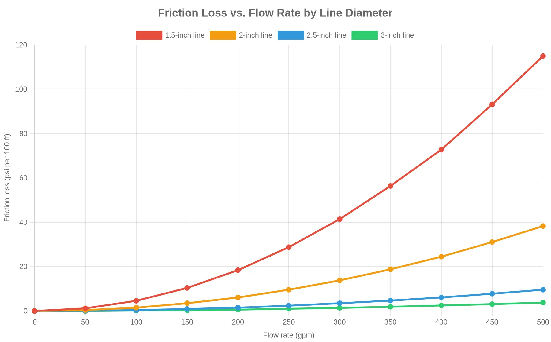
At the same flow rate, the smaller line loses far more pressure. That is how a factory decision, say in municipal and emergency service vehicles, ends up shaping real-world performance years later.
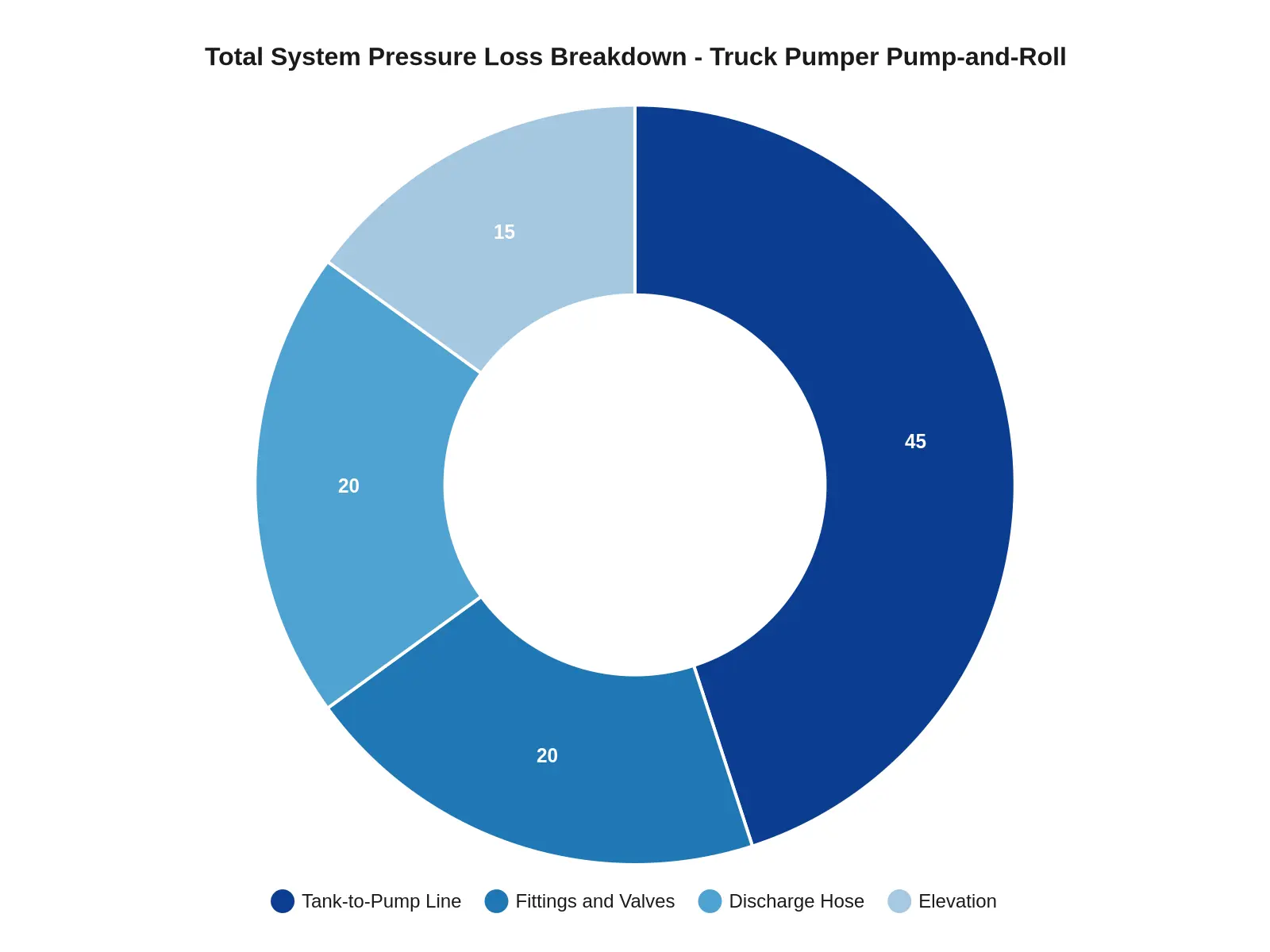
What Really Caps Flow Duration on a Truck Pumper
Flow duration in pump-and-roll comes down to hydraulics, not horsepower. Each of the following directly affects how long a crew can keep water on the fire from the tank:
- Tank capacity – total gallons onboard set the absolute ceiling; more water means a longer window before resupply is required.
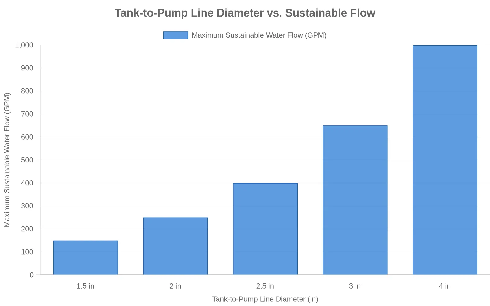
- Tank-to-pump line diameter – a larger internal diameter moves more volume at lower velocity, raising the sustainable flow rate.
- Tank-to-pump line length – longer runs add resistance; every extra foot takes usable flow.
- Friction loss – pipe roughness and turbulence convert pressure into wasted energy, cutting what reaches the nozzle.
- Fittings and valves – elbows, tees, and partly open valves add localized restrictions that compound friction loss.
- Required discharge pressure – higher nozzle or master-stream pressure takes more energy, shortening how long a fixed tank can sustain it.
- Required application rate – the gpm needed for knockdown sets the drain rate; higher rates empty the tank sooner.
Fix the plumbing before chasing rpm. The line, not the engine, decides how long you can flow.
| Tank-to-Pump Line Size (in) | Approx. Max Sustainable Flow (gpm) | Equivalent Flow Duration from 1,000 gal Tank (min) | Notes |
|---|---|---|---|
| 2.5 | 500 | 2.0 | NFPA 1901 sets a flow floor, not a diameter (500 gpm in the common case); at this size friction loss dominates and caps flow well below engine capability |
| 3 | 800 | 1.3 | Typical OEM compromise; diameter, not rpm, becomes the limiting restriction |
| 4 | 1,500 | 0.7 | Steep gain in attainable flow; pressure loss falls, so duration shortens sharply |
| 5 | 2,500 | 0.4 | Large-diameter plumbing; line is no longer the bottleneck, tank and pump govern |
| 6 | 3,500 | 0.3 | Effectively removes the line as a ceiling; achievable flow now set by tank and intake |
The Flow-Duration Arithmetic: Volume Divided by Flow Rate
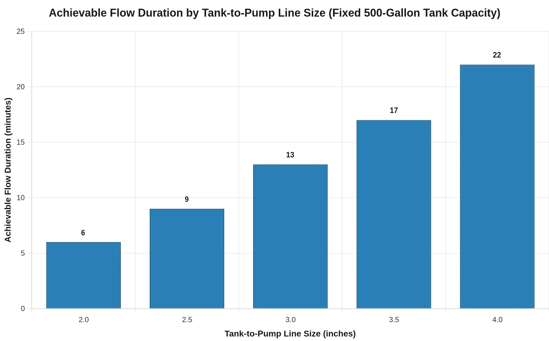
Flow duration is arithmetic, not throttle. One division governs it: usable tank volume divided by sustainable flow rate equals minutes of flow.
Minutes of flow = usable tank volume (gal) / sustainable flow rate (gpm)
Work an example.
Usable tank volume. A 500-gallon tank, less the unusable heel and reserve, leaves 450 gallons.
Sustainable flow rate. The tank-to-pump line passes at most 250 gpm. Pipe diameter, fittings, and bends set that ceiling.
Divide. 450 / 250 = 1.8 minutes.
Check the divisor. Raise engine rpm and the pump spins faster, but the tank-to-pump line is already at its flow limit. The divisor stays at 250 gpm and duration stays at 1.8 minutes.
The table runs the same division across a range of engine rpm values.
| Engine rpm | Pump speed | Tank-to-pump line flow rate | Flow duration (450 gal / rate) |
|---|---|---|---|
| 1,200 | Low | 250 gpm (line limit) | 1.8 min |
| 1,800 | Medium | 250 gpm (line limit) | 1.8 min |
| 2,200 | High | 250 gpm (line limit) | 1.8 min |
Once the tank-to-pump line reaches its flow limit, it is choked. Adding rpm raises pump vacuum and cavitation risk, not delivery, so the divisor does not move. To change flow duration, change what controls the divisor: usable tank volume or the line’s flow capacity. Both are engineering choices made when the tank and plumbing are built, not adjustments available from the pump panel.
Pump-and-Roll Flow: Common Questions
Can higher engine rpm extend pump-and-roll flow duration?
No. Throttling up raises pump speed and discharge pressure, but it cannot clear a plumbing bottleneck. If the tank-to-pump line is undersized, it reaches its hydraulic ceiling early, and more engine rpm only spins the pump against a starved inlet. The result is cavitation, air entrainment, and the same practical flow duration, just noisier and harder on the impeller. Duration is usable tank volume divided by achievable flow rate, not the operator’s throttle position.
Does a larger tank solve the problem?
Not on its own. A bigger tank adds storage, but if the tank-to-pump line still restricts flow you gain capacity without gaining discharge rate: the tank drains more slowly while the pump delivers less water than the fire needs. Sizing the tank and the feed line together is what extends effective pump-and-roll time.
How do you identify an undersized tank-to-pump line?
Start with pressure and vacuum readings. A large drop between static tank pressure and pump inlet, rising inlet vacuum under load, and falling flow as engine rpm rises all point to restriction. Confirm it in the field by comparing rated flow with measured flow, and by inspecting line diameter, fittings, and bend radius against the pump’s rated inlet demand.
Can modifications raise the flow ceiling?
Yes, but real gains come from reducing restriction, not from the throttle. Enlarging line diameter, removing restrictive elbows and valves, and cleaning strainers can lift the ceiling. Specifiers should verify line sizing during the apparatus build; teams evaluating municipal vehicle platforms can confirm feed-line ratings before delivery.
What maintenance keeps a tank-to-pump line at rated flow?
Keep the system at design capacity. Inspect and clean the strainer and tank outlet, check for collapsing, kinked, or delaminating hose, verify valve travel and open stops, and pressure-test the line on a schedule. Routine flow testing under live pump-and-roll conditions catches gradual clogging long before it compromises a fireground water supply.
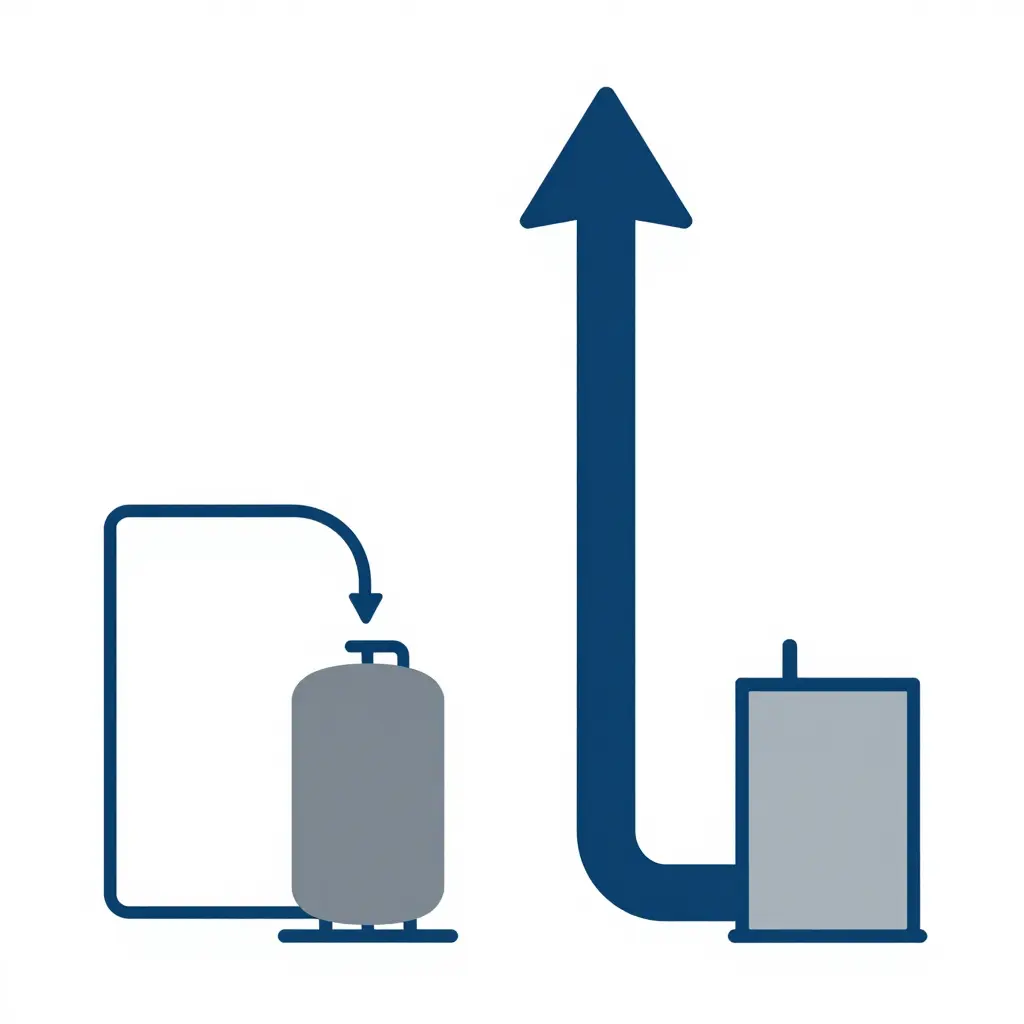
Figure 1. Two tank-to-pump configurations side by side. On the left, an undersized line feeds the pump with a small flow arrow, indicating a low achievable flow rate. On the right, an adequately sized line feeds the same pump with a larger, bolder arrow, indicating substantially more flow. Only line width and arrow thickness change, which isolates the variable that matters: the cross-sectional flow area of the line, not pump speed.
Sizing and Maintaining the Tank-to-Pump Line
An undersized tank-to-pump line caps pump-and-roll performance no matter how the operator works the throttle. For apparatus specifiers, dealers, and fleet maintenance managers, the line is a hydraulic decision first and an engine decision second.
Sizing for the required flow
Start with the flow you must deliver while moving, commonly 500 gpm straight from the tank and 750 to 1,000 gpm for sustained mobile water supply. Tank-to-pump lines are short, but diameter governs friction loss, and friction loss climbs with the square of flow. A 3-inch line moving 1,000 gpm sheds roughly 80 psi per 100 ft; a 5-inch line loses about 8 psi. Because the run is short, upsizing one nominal size can recover hundreds of gpm of usable flow at the nozzle. Whether you specify purpose-built fire apparatus or a broader municipal vehicle fleet, the discipline is the same: size the line for the maximum rated tank-to-pump flow with margin, then confirm the pump can actually pull that volume through the installed plumbing.
| Line ID | Friction loss at 500 gpm (psi/100 ft) | Friction loss at 1,000 gpm (psi/100 ft) |
|---|---|---|
| 3 in | 20 | 80 |
| 4 in | 5 | 20 |
| 5 in | 2 | 8 |
Verifying rated flow
Do not trust the placard alone. Flow-test the tank-to-pump line at rated pressure and record the delivered volume; a line that meets its number cold can fall short once the pump heats up, the tank level drops, or the strainer loads. Keep that baseline so future drift is easy to spot.
Keeping the line unrestricted
Restriction arrives gradually. Sediment, scale, collapsed or kinked sections, and clogged strainers act as hidden throttles that mimic an underpowered engine. Flush and inspect the line on a fixed interval, replace corroded fittings, and treat strainer cleaning as routine. The same clogging that sidelines liquid-waste vehicles will quietly take your pump-and-roll flow with it.
Conclusion
Pump-and-roll performance reduces to one chain of cause and effect. Engine rpm sets fire pump speed, which sets how fast the impeller spins and how much pressure the pump can develop at any instant. That is only half the picture. The tank-to-pump line, running from the booster tank to the pump intake, imposes a fixed hydraulic restriction set by its internal diameter, length, and fittings. Once that restriction establishes the flow ceiling, opening the throttle further only spins the pump faster without drawing more water from the tank. Sustainable flow duration is a plumbing problem, not a throttle problem. A larger engine cannot compensate for an undersized tank-to-pump line, and no driver-operator technique overrides the hydraulics.
For fire service professionals, the takeaway is direct: treat intake plumbing as a primary design and inspection variable, not an afterthought. When evaluating municipal and specialty vehicle platforms for pump-and-roll duty, size and verify the tank-to-pump line against realistic sustained-flow demands, confirm that valves and fittings do not reintroduce the restriction the pipe was meant to eliminate, and document the resulting flow ceiling for the crews who must work within it. Engine rpm sets the pace; the plumbing sets the limit.